ALD Ozone Delivery System Oxford Instruments Plasma Technology
Equipment Manual
DESCRIPTION
Printed: 14-Jul-10, 7:09
Page 3-1 of 6 Issue 01: July 10
3 Description
3
Description ............................................................................................................................ 3-1
3.1 General description.............................................................................................................3-2
3.1.1 System features............................................................................................................3-2
3.1.2 Use of delivery system..................................................................................................3-2
3.2 Main parts of the ozone delivery system .............................................................................3-2
3.3 Safety features ....................................................................................................................3-3
3.3.1 Safety interlocks...........................................................................................................3-3
3.3.2 Ozone monitoring ........................................................................................................3-3
3.4 Functional description of the ozone delivery system............................................................3-4
3.5 Pneumatic control circuit for the ozone delivery system ......................................................3-5
3.6 Electrical schematic.............................................................................................................3-6
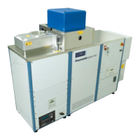
Figure 3-1: Ozone generator cabinet .............................................................................................3-2
Figure 3-2: Functional diagram of the ozone delivery system .........................................................3-4
Figure 3-3: Pneumatic control circuit .............................................................................................3-5



 To Next Page