Form PA102.20-N1
31
Installation & Assembly Manual │ PACESECTION 3 - HANDLING, STORAGE, AND INSTALLATION
Issue Date: 07/03/2018
3
CONNECTORS
Figure 24 - Electrical Connectors (Connected)
LD13374
8. After making the electrical and control connec-
tions and before proceeding with assembly, re-
move and reposition the top shipping split angle
as shown in Figure 25 on page 31.
Figure 25 - Remove and Reposition Shipping Split
Angle
LD14097
Setting Up the Sections
Use the following instructions to set up the sections.
1. Place the rst section on the curb. Position it so
that the overhanging curb rest is spaced evenly
from the curb on each side and end.
2. After the rst section is placed, anchor, or block it
before setting the next section.
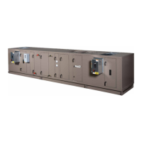
3. Attach the come-a-longs (power pulls) as shown
in Figure 22 on page 31 to the rst section. Use
lifting lugs on the base rail (not at the shipping
split) or holes in the two outside corners.
LD09613a
Figure 22 - Typical Come-A-Longs
4. Apply a 1/2 in. thick bead of caulk to the curb top
surface in the area where the next section will be
placed.
5. Place the next section on the curb about 4 in. from
the rst section.
6. Feed the electrical and control connections from
section to section and make sure that they will be
accessible after the sections are joined as shown
in Figure 23 on page 31.
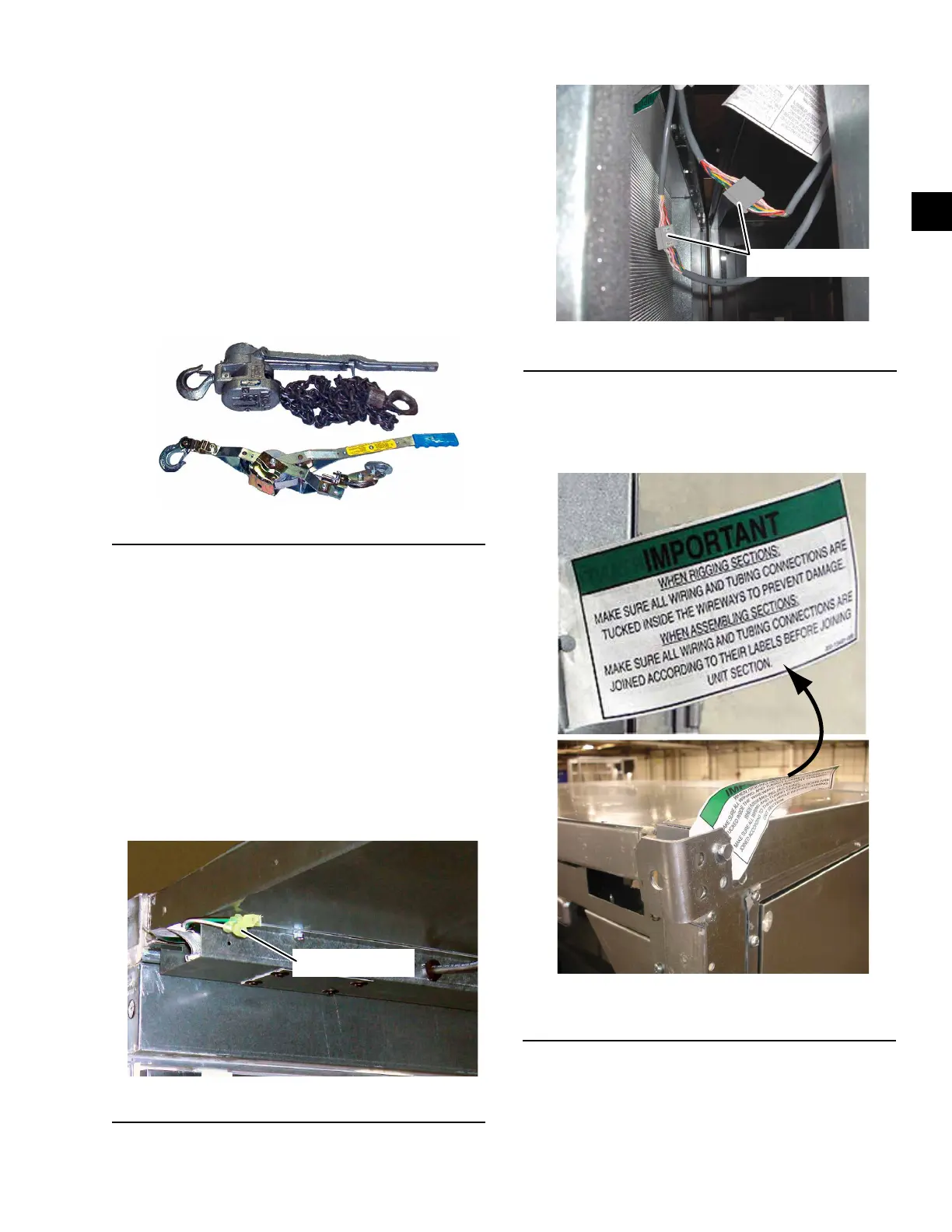
7. Assemble the electrical connectors and/or pneu-
matic tubes as shown in Figure 24 on page 31
according to their labels before joining sections, if
access will be a problem later.
LD13373a
Figure 23 - Electrical Connector (Not Connected)
CONNECTOR