SECTION 3 - HANDLING, STORAGE, AND INSTALLATIONPACE │ Installation & Assembly Manual
Issue Date: 07/03/2018
54
Form PA102.20-N1
Installing a 2 in. and 4 in. Pre-Filter
Combined with a DH Final Filter
Use the following instructions to install a 2 in or 4 in
Multi-Pleat Elite or MicroMAX pre-filter combined with
a Multi-Cell SBM DH (nominal 12 in. deep) final filter
into a 16 g galvanized holding frame. Use the following
latches to install the lter and pre-lter:
• Four spring latches (P/N 026-35788-612) to hold
the Multi-Cell SBM DH into the frame,
• Four pre-lter latches (P/N 026-35788-625) to
hold the 2 in. latch, and
• Four pre-lter latches (P/N 026-35788-626) to
hold the 4 in pre-lter onto the face of the Multi-
Cell SBM DH lter.
1. Install the two latches on each side of the frame,
not on the top or bottom.
2. Insert the straight end of the latch between the
two knockouts furthest from the corner.
3. Using a moderate amount of pressure, force the
latch over the third knockout.
4. The latch installation should now be complete.
The latch should now be trapped within the three
knockouts as shown in Figure 84 on page 54.
LD10154
Figure 84 - Correct Latchout/Knockout Configuration
(P/N 026-35788-612)
5. Repeat the steps with the remaining latches. Note
the orientation of the latch to the knockouts as
shown in Figure 84 on page 54.
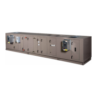
6. Insert the Multi-Cell SBM DH lter into the frame.
While holding the lter in the frame, grasp the loop
on the end of the latch, and pull it until it stretch-
es over the header, and rests into the pre-drilled
hole in the header as shown in Figure 85 on page
54.
LD10184
Figure 85 - Spring Latch Pulled and Fastened in Filter
Hole
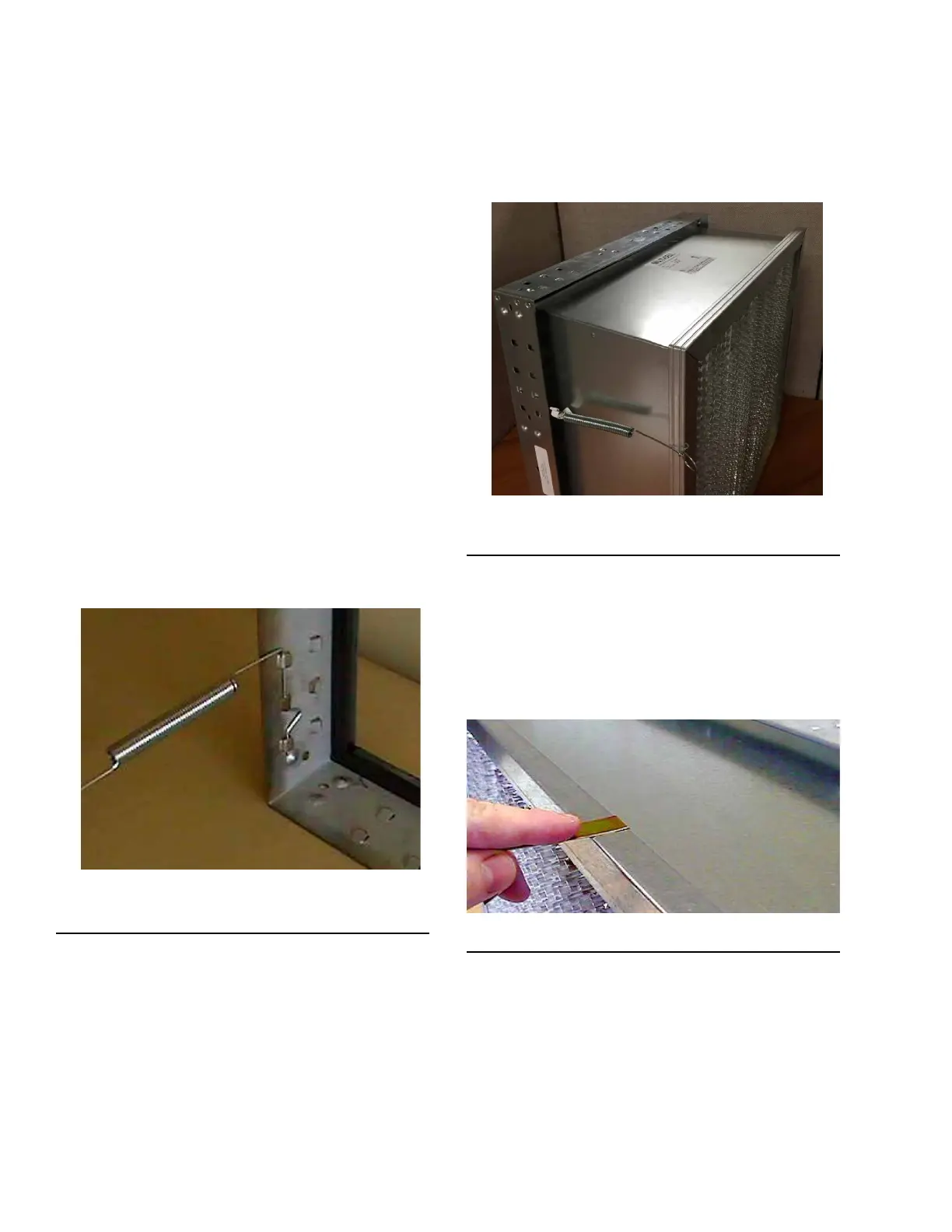
Installing Pre-Filter Latches
1. To install the pre-lter latches, slide the end of the
latch with a 180° turn over the edge of the header,
as shown in Figure 86 on page 54. Install the
latch at the approximate midpoint of the lter leg.
The pre-lter latch should be slid over the header
as shown in Figure 86 on page 54.
LD10163
Figure 86 - Installing Pre-Filter Latch
2. Repeat the steps for the remaining pre-lter latches.