SECTION 3 - HANDLING, STORAGE, AND INSTALLATIONPACE │ Installation & Assembly Manual
Issue Date: 07/03/2018
34
Form PA102.20-N1
MOISTURE
ELIMINATOR
CLIP
BUTYL
TAPE
CAULK
LD13783
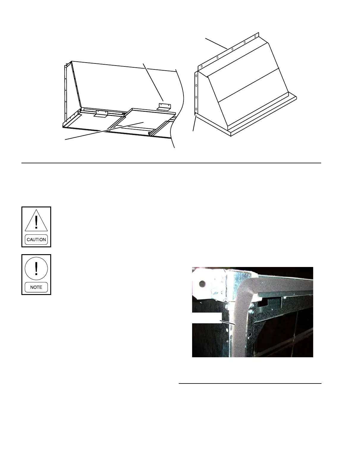
Figure 31 - Installing Hood with Optional Moisture Eliminators
5. Remove the plastic shipping covers and supports.
6. Apply neoprene gasket (P/N 028-15954-010) to
one side only of each shipping split as shown in
Figure 32 on page 34. If there is a door frame
at the shipping split, apply neoprene gasket (P/N
028-11873-010) as shown in Figure 33 on page
35. Make sure the entire perimeter is covered
with the gasket material, including the foamed
corners as shown in Figure 33 on page 35. Any
void, depression, or protrusion will allow air or wa-
ter leakage. Make any splices on a straight run.
LD13779
Figure 32 - Use Gasket (P/N 028-11883-010) at
Shipping Split
GASKET
INSTALLING INDOOR AHU
Before installing the indoor AHU, identify the shipped
loose parts such as gaskets as shown in Figure 52 on
page 43 through Figure 70 on page 46.
Do not damage factory installed pipe
chase, electrical cabinet, hoods, pipe
stubs, door handles or roof overhang
when installing AHU.
If the AHU or AHU sections are too
large to t through an opening, contact
the local PACE Field Service Ofce for
assistance. Technical instructions are
available for disassembly and reas-
sembly.
Before placing the skids together:
1. If applicable, remove the metal bracket attached
to the cross channel and wood shipping blocks
before assembling the shipping splits.
2. If AHU sections are going to be assembled before
placing them, be sure the sections are on a at
surface during assembly.
3. Verify the correct sections and orientation of each
section.
4. Remove the cross brace(s) (shipping supports)
from each section’s shipping split.