Form PA102.20-N1
75
Installation & Assembly Manual │ PACESECTION 3 - HANDLING, STORAGE, AND INSTALLATION
Issue Date: 07/03/2018
3
INSTALLING EXTERNAL VENT PIPING
FOR OUTDOOR AHUS
For outdoor AHUs with an overall
height less than 102 in (8 1/2 ft), the
external vent piping parts will be fac-
tory installed.
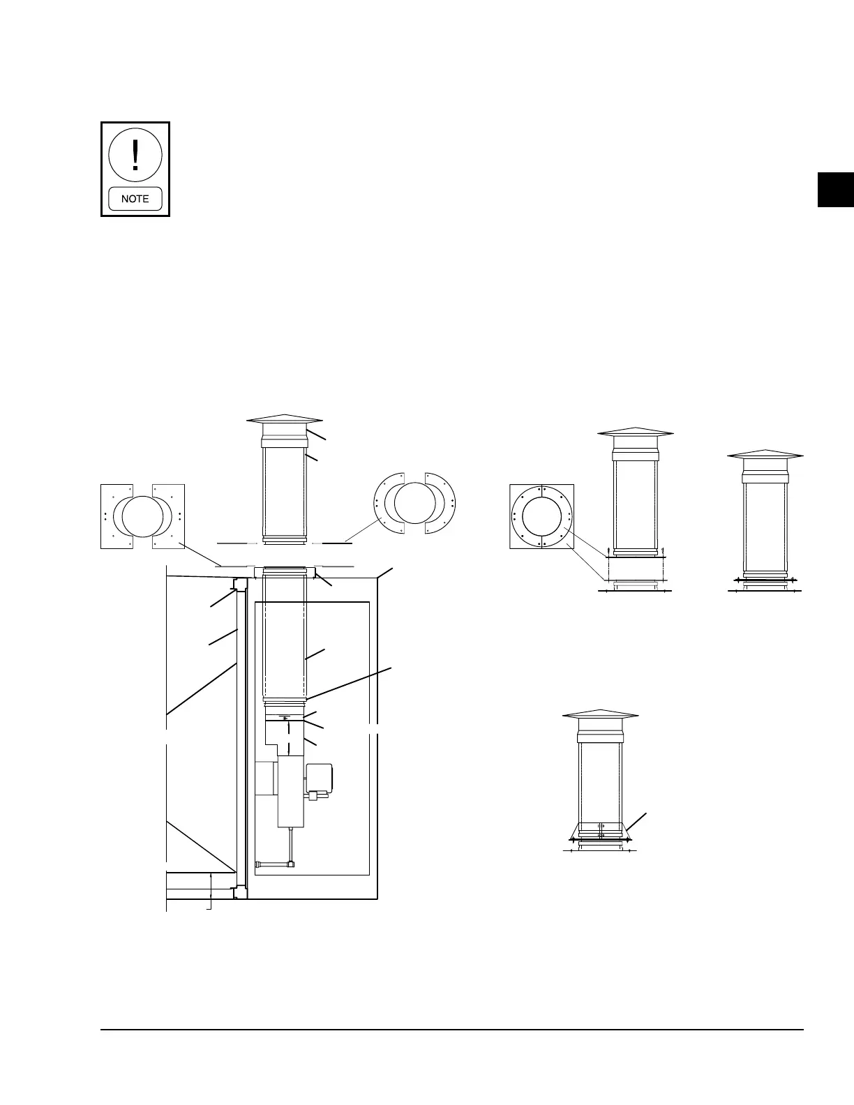
For outdoor AHUs with an overall height more than
102 in. (8 1/2 ft), the external vent piping parts will be
shipped loose for field mounting. Figure 126 on page
75 shows some generic instructions to install the
piping parts. An installation manual specific to the fuel
venting system will be provided.
Condensate Drain Arrangement
The indirect fired gas heat exchanger has the poten-
tial to create highly acidic condensation, particularly
during extended operation at low capacity or low firing
rate conditions. To insure proper drainage, use the fol-
lowing instructions as shown in Figure 127 on page
76.
When constructing the condensate trap for the heat
exchanger drainage system, make sure the trap is tall
enough to handle the total static pressure (TSP) of the
indoor blower at low fire times. For example, if a TSP
is 6 in. at low fire, construct a trap that is 12 in. tall as
shown in Table 7 on page 76.
12
EXT.
7.75
FLUE CAP
VSI PIPE
SPLIT CLAMP
PIPE CHASE
SPLIT PLATE
RACEWAY
SIDE
PANEL
GAS FURNACE WITH CASING
HAT CHANNEL
ID
FAN
TRANSITION
PIECE
0.43 IN CLEARANCE
IVSI PIPE
SLIP JOINT
CURB
PIECE
CONTAINMENT
BAND SET, GASKET
AND INSULATION
FIBER
STORM COLLAR
STEP 1
STEP 2
STEP 3
STEP 4
LD13326
Figure 126 - Gas Furnace Fuel Venting System