38
Establishing electrical connections
8.2 Installing and connecting the control unit
The optional control unit must be mounted in a suitable location in
the driver's cab.
If a control unit is already present in the vehicle, you must connect
your PALFINGER Tail Lifts tail lift according to a special circuit di-
agram, which you can obtain from PALFINGER Tail Lifts.
Run the cable for the control unit to the driver's cab.
Select a suitable location on the dashboard in the driver's cab.
Establish an electrical connection as per the PALFINGER
Tail Lifts circuit diagram.
Mount the control unit on the dashboard.
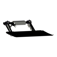
8.3 Mounting the control panel holder
Fix the control panel holder with screws or weld it in position as
per the PALFINGER Tail Lifts assembly diagram.
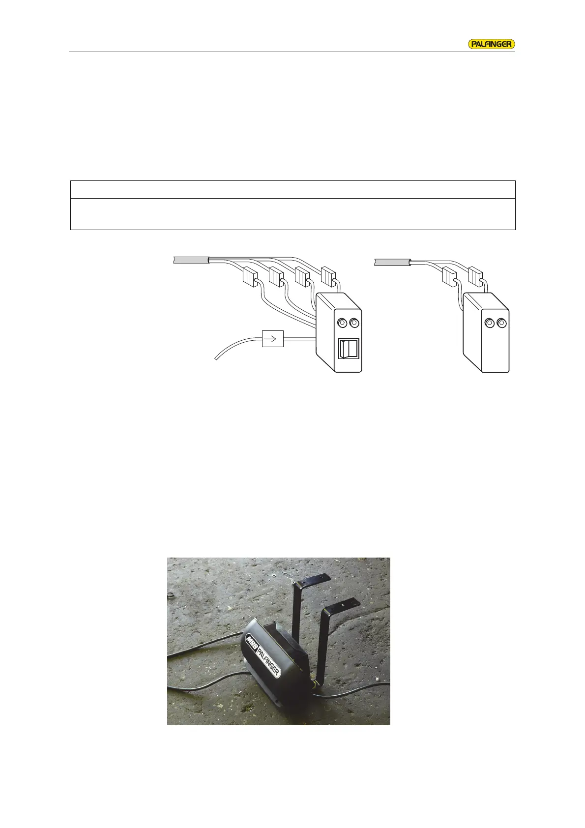
NOTE
Connection of the control device must not take place until the electrical connection
of the plus and minus cable has taken place.
optional:
connection for starting block
max. 0.25 A
421
ye
gn
(−)
1
ye
gn
(−)
bs3
 Loading...