23
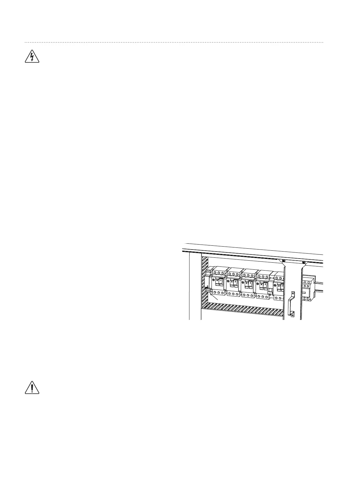
12. Electrical connections
WARNING: BEFORE CARRYING OUT ANY WORK ON THE EQUIPMENT,
MAKE SURE THAT THE ELECTRICAL POWER SUPPLY IS DISCONNECTED
AND THAT THERE IS NO POSSIBILITY OF THE UNIT BEING STARTED
INADVERTENTLY.
NON-COMPLIANCE WITH THE ABOVE INSTRUCTIONS CAN LEAD TO
INJURY OR DEATH BY ELECTROCUTION.
The electrical installation must be performed by a fully qualifi ed electrician, and in accordance with local electrical standards
and the wiring diagram corresponding to the unit model.
Any modifi cation performed without manufacturers prior authorisation may result in the unit’s warranty being declared null and
void.
The power supply cable section must be suffi cient to provide the appropriate voltage to the unit’s power supply terminals, both
at start-up and under full load operating conditions.
The power supply cable shall be selected in accordance with the following criteria:
1. Power supply cable length.
2. Maximum unit operating current
3. Maximum unit starting current draw
4. Power supply cables’ installation mode.
The use of a fuse to protect the units against short circuits is recommended. The fuse sizes are displayed in the table in §
“Electric specifi cations”, page 13
Very important:
3N~400V-50Hz
The outdoor unit is equipped as standard with a phase sequence and cut-out controller located in the electrical box.
The LED’s indicate the following
conditions:
Green LED = 1
Yellow LED =1
Power ON
The compressor rotation direction is
correct.
Green LED = 1
Yellow LED =0
Phase inversion or phase absent (L1)
The compressor and the fans do not start.
Green LED = 0
Yellow LED =0
Phase absent (L2 or L3)
The compressor and the fans do not start.
CAUTION
Before connecting the supply lines, check that the voltage available is within the limits specifi ed (Refer to
the § “Electric specifi cations”, page 13).
Voltage differences between each phase must not exceed 2 %.
If the imbalance is unacceptable, call the distribution company to have this anomaly corrected.
KA1