30
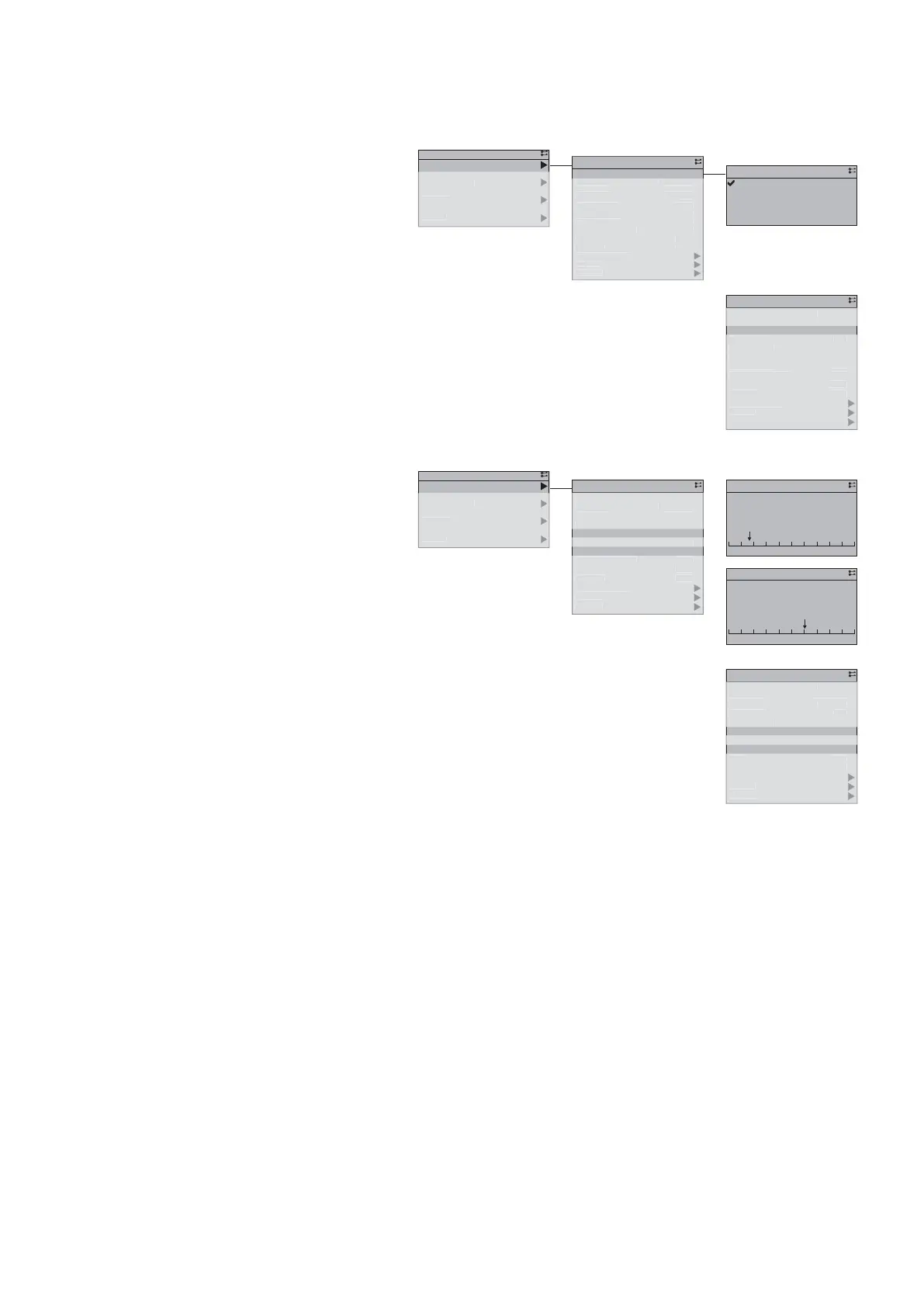
13.4.4. Selecting the operating mode
To launch the unit, the user must select the desired mode in the menu:
• Delegate: the current mode is determined by
the BMS or by default by the calendar (refer to
the user manual)
• Off: Unit is stopped
• On: System is launched
• Reduced: Refer to the § “Reduced mode”,
page 35
• Limited capacity: Refer to the § “Limited
capacity”, page 35
The “State from” line states which element requested the current status:
• Cont.off: on/off digital input
• Cont.ext: D2 confi gurable digital input (in “Reduced mode” or “Limited capacity”
• HMI: User interface
• BMS
• Schedul
13.4.5. User temperature setpoints and actual setpoints
In the Status menu, the user can set start or
return temperature setpoints, according to the
control mode selected:
• Cooling setp: temperature setpoint for the cool
mode
• Heating setp: temperature setpoint for the heat
mode
These setpoints are fi xed and restricted to the
unit’s operating limits.
They can however be adjusted with the “Water
law” and “Reduced mode” options, which are
deactivated by default.
Regardless of the adjustment, the resulting setpoint is restricted to the operating limits to protect
the unit.
Actual heat and cooling setpoints correspond to values used in real time, account taken of any
adjustments and protections.
1
13
,0
,0
4°
4°
0°C
,0°C
MI
chedul.
utomat
c
ele
ate
ircuit 2
ircuit 1
draulic circuit
apacit
oa
urrent setp. heat
eatin
setp.
Current setp. cool
Coolin
setp.
tate from
r
m
MI
t
t
mo
e
tatus
1/13
44°C
44°C
8,0°C
8,0°C
HMI
Schedul.
Automatic
Delegate
Current setp. heat
Heating setp.
Current setp. cool
Cooling setp.
State from
Mode from
HMI state
HMI mode
Status
1
13
0
,0
4°
4°
0°C
,0°C
MI
chedul.
t
m
t
ele
ate
ircuit 2
ircuit 1
draulic circuit
apacit
oa
Current setp. heat
eatin
setp.
Current set
. cool
Coolin
setp.
tate from
r
m
MI
t
t
m
tatus
1/13
Schedul.
Automatic
Delegate
State from
HMI state
HMI mode
Status
4
ervice
ommissioning
tatu
M
in M
n
1
13
0
0%
0
0%
4°
4°C
8
0°
8
0°C
chedul.
utomat
c
e
e
at
ircuit
ircuit
y
rau
c c
rcu
t
Capacit
oa
urrent setp. heat
eat
n
setp.
urrent setp. cool
oolin
setp.
tate fro
ode
rom
state
MI m
tatu
1/13
Delegate
HMI state
Status
1/5
Limited capacity
Reduced
On
Off
Delegate
HMI state
✔
✔
18,0°C4,0°C
8,0°C
55,0°C20,0°C
44,0°C
4
cces
Service
ommissioning
tatu
M
in M
n
1
13
0,0
0,0
4°
4°
8,0°C
8,0°C
chedul.
utomat
c
Dele
at
ircuit
ircuit
y
rau
c c
rcu
t
Capacit
urrent setp. heat
eatin
setp.
urrent setp. cool
oolin
setp.
tate fro
ode
rom
t
t
mo
e
tatu
1/13
44°C
8,0°C
8,0°C
HMI
Schedul.
Automatic
Delegate
Heating setp.
Current setp. cool
Cooling setp.
State from
Mode from
HMI state
HMI mode
Status
✔