1. Servicing fixtures & tools............................................................................................................. INF-1
2. Maintenance................................................................................................................................ INF-3
2-1. Maintenance Schedule.......................................................................................................INF-3
2-2. Confirmation method of operation number of times ........................................................... INF-3
2-3. Reset of operation number of times ................................................................................... INF-3
2-4. Replacement procedure of Zoom Motor unit...................................................................... INF-3
3. Lithium battery............................................................................................................................. INF-4
3-1. Replacement Procedure..................................................................................................... INF-4
4. Service menu............................................................................................................................... INF-6
4-1. DIAGNOSTIC menu...........................................................................................................INF-7
4-1-1. Model No., Serial No. Display ................................................................................. INF-7
4-1-2. Software Version Display. ....................................................................................... INF-7
4-1-3. 1394 UID Display..................................................................................................... INF-9
4-1-4. Error reset of XP Micon/EEPROM. ......................................................................... INF-9
4-1-5. Display of ZOOM MOTOR operation number of times. .......................................... INF-10
4-1-6. SHUTTLE SPEED Select........................................................................................ INF-10
4-1-7. Update..................................................................................................................... INF-10
4-2. ADJUST menu ................................................................................................................... INF-11
4-2-1. Adjustment item for Video Level.............................................................................. INF-11
4-2-2. Adjustment method for Video Level ........................................................................ INF-11
4-2-3. LCD Correction........................................................................................................ INF-12
4-2-4. EVF Correction........................................................................................................ INF-12
5. PC EVR software (VVS0070)...................................................................................................... INF-13
5-1. Required tools and equipment for PC EVR software ......................................................... INF-13
5-2. Connection.......................................................................................................................... INF-13
5-3. Setup of PC EVR software ................................................................................................. INF-16
5-4. Setting Tool screen............................................................................................................. INF-17
5-4-1. Setting and confirmation of Date and Time of internal clock(SYSCON(S
) section) INF-18
5-4-2. Hour Meter Display(SYSCON(S
) section)............................................................... INF-18
5-4-3. Software Version Display(SYSCON(S
) section)..................................................... INF-19
5-4-4. Power supply reboot(SYSCON(S
) section)............................................................. INF-19
5-4-5. Display of ZOOM MOTOR operation number of times(CAM(C
) section) ............... INF-20
SERVICE INFORMATION
Model No. :
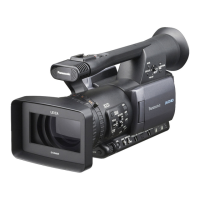
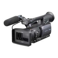
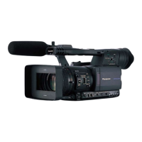
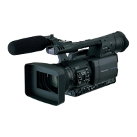
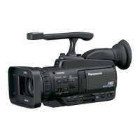
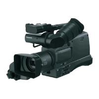
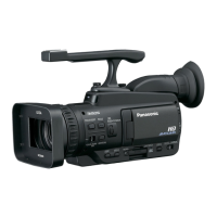
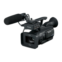
AG-HMC150P/AN, AG-HMC151E, AG-HMC152EN
CONTENTS
AG-HMC153MC, AG-HMC154ER



 Loading...