2-17
3-9. Photo Sensor Voltage
Adjustment
SPEC See below
TEST POINT Refer to item “2. Table of Test
Point”
ADJ. Refer to item “2. Table of Test
Point”
MODE STOP
TAPE VFK1423
(Tape Beg./End M Cassette)
VFK1369
(Tape Beg./End L Cassette)
M. EQ Oscilloscope
(Specification)
TYPE Specification of voltage
A A = 3.1 VDC ± 4.2 VDC
B A = 3.2 VDC ± 0.8 VDC
C A = 2.2 VDC ± 0.6 VDC
(Classified list of specification)
TYPE Model
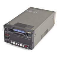
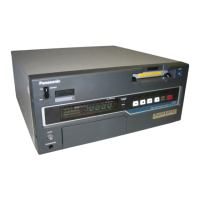
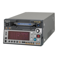
A AJ-D440, AJ-D450, AJ-D640, AJ-D650,
AJ-D750, AJ-D780, AJ-D850, AJ-D940,
AJ-D950, AJ-D950A, AJ-DE77
B AJ-D200, AJ-D210, AJ-D215, AJ-D610
AJ-D810, AJ-D90, AJ-D900W
AJ-D900WA, AJ-PD900W
C AJ-D220, AJ-D230, AJ-D230H, AJ-D250,
AJ-D92, AJ-D94, AJ-D95DC, AJ-LT75
AJ-LT85
1. Insert the VFK1423 or VFK1369 (in case of AJ-
D200, AJ-D210 and AJ-D215) and measure the
voltage at Test Point.
2. Adjust the adjustment VR or Dip SW so that the A
portion of DC voltage is within the specification as
shown in figure 3-9-1.
Figure 3-9-1
NOTE 1 :
If the model apply to TYPE A, please confirm that the
value of resistor R11 and R12 are 8200 ohm on
SYSCON (F2) P.C.Board before perform this
adjustment.
NOTE 2 :
Photo sensor voltage is adjusted by Dip SW200 about
Type A models. How set the bit of Dip SW for
adjustment indicated as below figure 3-9-2.
Figure 3-9-2
SW200
 Loading...