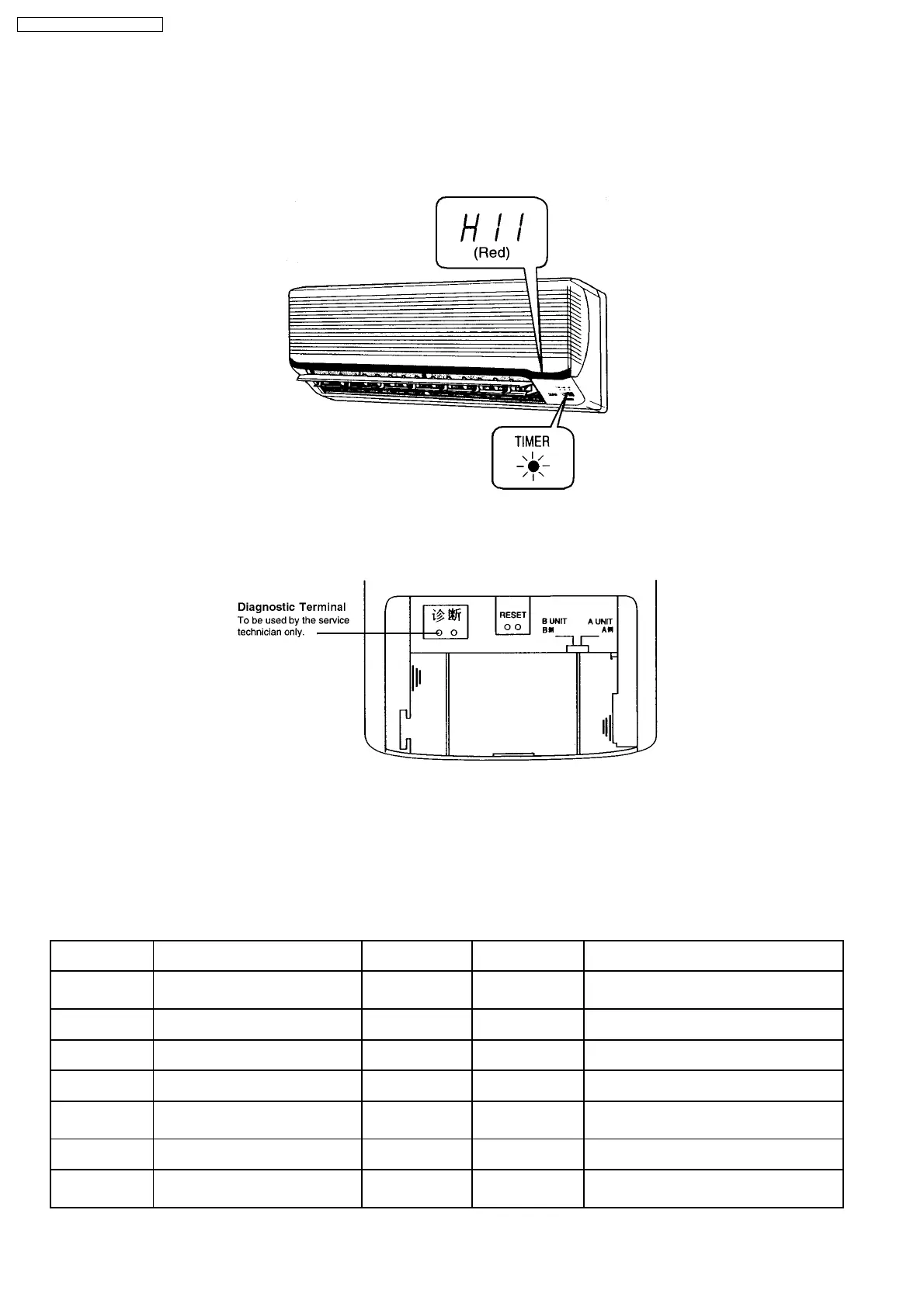
12.2. SELF DIAGNOSIS DISPLAY
The diagnostic display can be seen on the receiver of the Front Grille.
·
When an abnormality occurs, the unit automatically stops, and the TIMER LED blinks to indicate a malfunction. At the same
time, the type of abnormality will be indicated on the receiver as shown in the diagram below. Providing this information reduces
the time spent in diagnosing procedures.
·
The diagnostic display vanishes when the power is turned off.
·
When power is re-supplied and the Diagnostic Terminal on the Remote Control is shorted, the type of the previous abnormality
and the protection control works will be displayed on the receiver for approximately 10 seconds.
·
By starting cooling operation using TEST RUN button and short the Diagnostic Terminal at the remote control, the previous
abnormalities are deleted.
·
Depending on the type of abnormality, you may be able to override the abnormality and use temporary operation (for
abnormalities indicated by “●” mark in the table below).
Use the remote control to select cooling or heating operation mode and press OFF/ON button. At this moment, four short beeps
"bip.bip.bip.bip" will sound and TIMER LED will blink.
Diagnosis display Abnormality/Protection control Abnormality
Judgement
Temporary
operation
Primary location to verify
H11 Indoor/outdoor abnormal
communication
1 min after starting
operation
-
·
Internal/external cable connections
·
Indoor/Outdoor PCB
H12 Indoor unmatched capacity
abnormality
-
·
Indoor Unit
H14 Indoor intake air temperature sensor
abnormality
-
·
Intake air temperature sensor (defective
or disconnected)
H15 Outdoor compressor temperature
sensor abnormality
-
·
Compressor temperature sensor
(defective or disconnected)
H16 Outdoor Current Transformer open
circuit
-
·
Outdoor PCB
·
Power transistor module
H17 Outdoor sustion pipe temperature
sensor abnormality
-
·
Outdoor suction pipe temperature sensor
(defective or disconnected)
H19 Indoor fan motor mechanism lock -
·
Indoor PCB
·
Fan motor
58
CS-MVG103KE / CU-MVG153KE