Before the circuit diagram, read the following carefully.
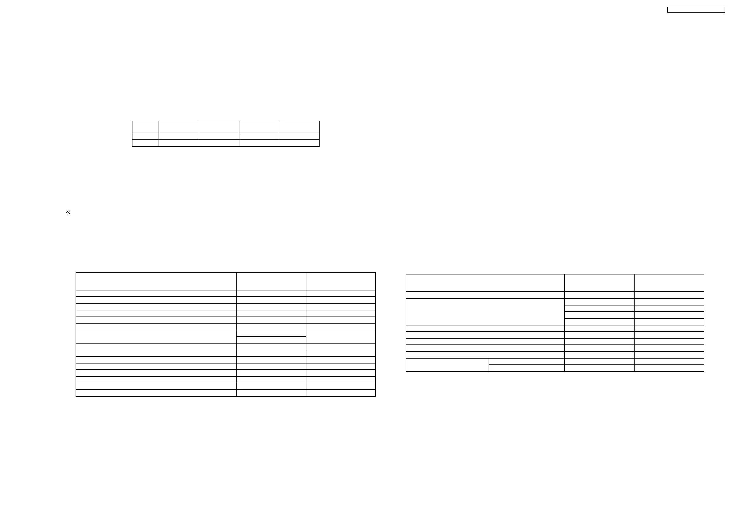
Voltage measurement
voltage has been measured with a digital tester when the indoor fan is set at high fan speed under the following conditions
without setting the timer.
Use them for servicing.
Voltage indication is in Red at cooling and all operations.
Voltage indication is in (Red) at heating.
Intake air
temperature
Temperature
setting
Discharge air
temperature
Pipe
temperature
Cooling 27°C 16°C 17°C 15°C
Heating 20°C 30°C 40°C 50°C
Indications for capacitor
a. Unit µ .... µF P .... pF
Indications for resistance
a. K .... K
Ω
M .... M
Ω
W .... wait Not indicated .... 1/4 W
Diode without indication ............ MA165
Circuit Diagram is subject to change without notice for further development.
14.2.1. Indoor
Name Time Test Mode
(When test point Short-
circulated)
4 way valve abnormality 4 min. 0
Outdoor air temp. for Hz No. detection 30 min. 0
Anti-freezing Control 6 min. 0
Theorem OFF delay 3 min. 0
Low pressure control ( gas leakage ) compressor OFF time 2 min. 0
Time delay safety control 2 min. 58 sec. 0
Odor timer status shift time 30 sec. 0
60 sec.
Hz lock time 30 sec. 0
Self diagnosis display time 10 sec. 0
Auto mode judgement sampling time 58 sec. 0
24 hours ON / OFF timer 1 hour
→
1 min.
Hot start forced completion 4 min. 0
Auto mode judgement interval 180 min. 180 sec.
Sleep mode time shift 1 hour
→
6sec.
After Hot start / Deice 2 min. 12 sec.
14.2.2. Outdoor
Name Time Test Mode
(When test point Short-
circulated)
DC PEAK 30 sec. 3 sec.
Deice detection 120 min. 24 sec.
80 min. 18 sec.
40 min. 8 sec.
40 min. 8 sec.
Deice forced completion 11 min. 66 sec.
Time delay safety control 3 min. 0
Hz lock time 30 sec. 0
Outdoor fan delay operation control 30 sec. 0
4 way valve delay operation control 3 min. 0
Standy control ON 3 min. 18 sec.
OFF 7 min. 42 sec.
14 Electronic Circuit Diagram
14.1. HOW TO USE ELECTRONIC CIRCUIT DIAGRAM
14.2. TIMER TABLE
CS-MVG103KE / CU-MVG153KE
71