10.1.3. CHECKING AND REPLACING OF DVD-RAM DRIVE / DIGITAL P.C.B. MODULE
1. Top Case
· Remove 4 Screws (A) on side and 3 Screws (B) on rear side.
· Remove Top Case.
2. Front Panel
· Remove one Screws (A) on center.
· Unlock 2 Locking Tabs (A), (D) on Front Panel side and 2 Locking Tabs (B), (C) on Front Panel topside.
· Unlock 2 Locking Tabs (E) on Front Panel bottom side and remove Front Panel.
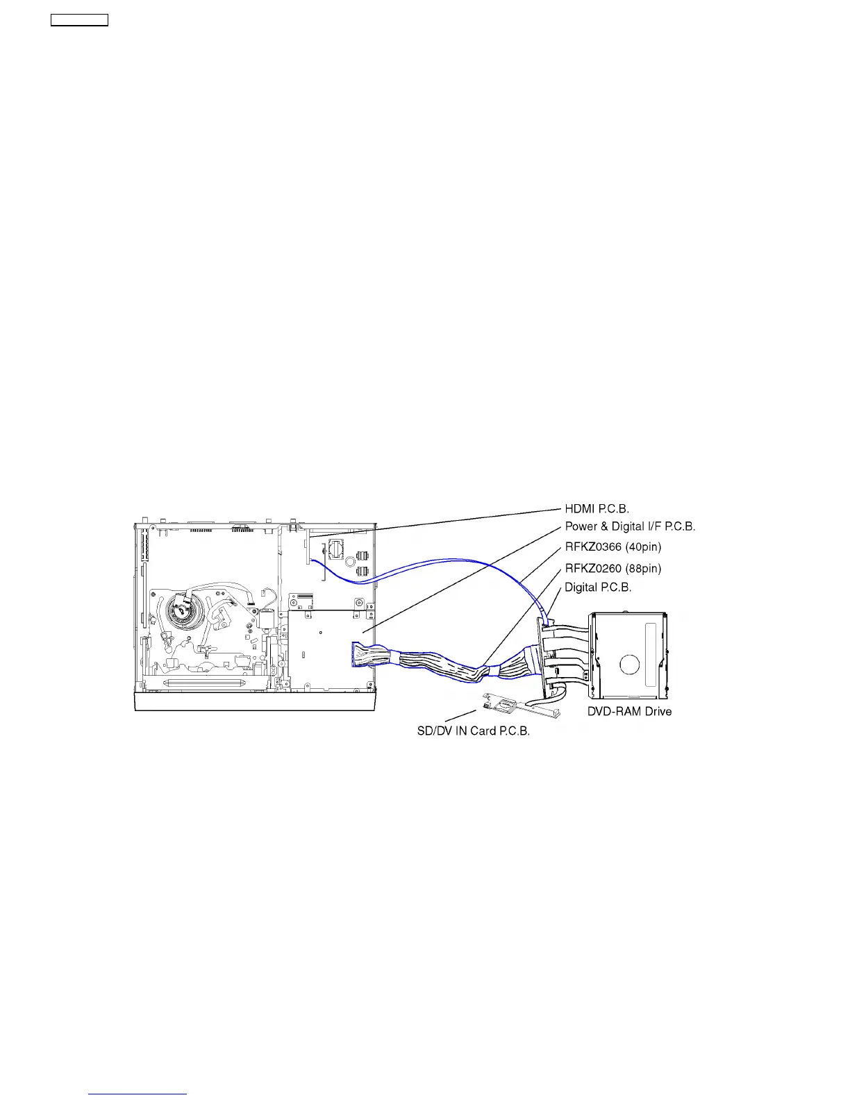
3. DVD-RAM Drive / Digital P.C.B. Module
· Remove the 5 Screws.
· Lift up and hold the DVD-RAM Drive (together with DVD Angle) slightly.
· Remove FF Cable from SD/DV IN Card P.C.B.
· Remove 4 screws from Digital P.C.B. (pay attention while pulling out Digital P.C.B. to disconnect Connector).
· Remove the Digital P.C.B. together with the DVD-RAM Drive and put it beside chassis.
· Remove 2 Screws from SD/DV IN Card P.C.B., take P.C.B. out and attach FF Cable back to Digital P.C.B.
· Attach the Front Panel back to the Chassis.
· Connect Extension Cables:
− between Power & Digital I/F P.C.B. and Digital P.C.B. with RFKZ0260 (Red Wire = Pin 1)
− between Power & Digital I/F P.C.B. and HDMI P.C.B. with RFKZ0366
CAUTION:
The DVD-RAM Drive and the Digital P.C.B. have to be replaced together as one Module.
If the Module is changed the DVD-RAM Drive has to be re-aligned because the aligment data
for the DVD-RAM Drive is stored in the Digital P.C.B.
38
DMR-EZ45VEB
 Loading...