−
B27
−−
B26
−
English
3. System Conguration and Wiring
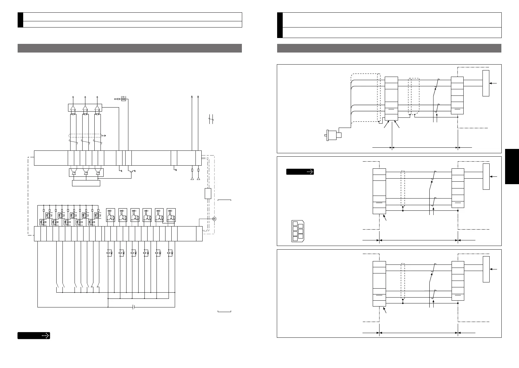
Wiring to the connector, X6
Connection to Encoder
•Incaseof20-bitincrementalencoder
MSMD 50 W to 750 W
MHMD 200 W to 750 W
MSME 1.0 kW to 5.0 kW
MDME 1.0 kW to 5.0 kW
MFME 1.5 kW to 4.5 kW
MGME 900 W to 4.5 kW
MHME 1.0 kW to 5.0 kW
Shell (FG)
+5 V
0 V
1
2
3
4
5
6
4
1
3
7
Twisted pair
Encoder cable
Connector: JN2DS10SL1-R
(by Japan Aviation Electronics Ind.)
Motor Driver
E5V
E0V
PS
PS
9
PS
PS
FG
E5V
E0V
X6
Regulator
X6
Shell (FG)
Motor
1
2
3
4
5
6
4
5
2
3
6
E5V
E0V
E5V
E0V
PS
PS
FG
PS
PS
DriverMotor
+5 V
0 V
Junction cable
172160-1
(by Tyco Electronics, AMP)
172168-1
(by Tyco Electronics, AMP)
White
Twisted pair
Black
Purple
Light blue
Regulator
Shell (FG)
+5 V
0 V
1
2
3
4
5
6
6
3
7
4
Twisted pair
Encoder cable
Connector: JN6FR07SM1
(by Japan Aviation Electronics Ind.)
Motor Driver
E5V
E0V
PS
PS
1
PS
PS
FG
E5V
E0V
X6
Regulator
MSME 50 W to 750 W
Tighten the motor connector
mounting screw (M2) with a torque
between 0.19 and 0.21 N
•m.
To avoid damage, be sure to use
only the screw supplied with the
connector.
[Connector pin assignment]
(Viewed from cable)
2
5
1
3
6
4
7
Wiring Example of Internal Velocity Control Mode
3. System Conguration and Wiring
Wiring to the connector, X4
SP
IM
1 kΩ
1 kΩ
FG
50
43
42
X4
( represents twisted pair.)
A-phase output
B-phase output
Z-phase output
Velocity monitor output
Torque monitor output
7
COM+
INH
CL
SRV-ON
GAIN
DIV1
ZEROSPD
C-MODE
A-CLR
POT
NOT
S-RDY+
S-RDY
-
ALM+
AT-SPEED
+
BRKOFF
+
BRKOFF
-
TLC
VDC
12 to 24 V
ZSP
COM
-
AT-SPEED
-
ALM
-
33
30
29
27
28
26
32
31
9
8
35
34
37
36
39
38
11
10
40
12
41
Servo-ON input
Gain switching input
Alarm clear input
Servo-Ready output
Servo-Alarm output
At-speed output
External brake release output
Torque in-limit output
Zero speed detection output
Speed zero clamp
input
Control mode
switching input
Positive direction
over-travel inhibition input
Negative direction
over-travel inhibition input
4.7 kΩ
OA+
OA
-
OB+
OB
-
OZ+
OZ
-
GND
CZ
21
22
48
24
25
19
49
23
Z-phase output (open collector)
GND
17
The functions of the following pin can be changed using parameters.
Input: 8, 9, 26, 27, 28, 29, 30, 31, 32, 33
Output: 10-11, 12, 34-35, 36-37, 38-39, 40
Remarks
X1toX7areusedforthesecondarycircuit.Toconnecttheseterminalstotheprimary
powersupply(particularly,the24VDCpowersupplyforbrake),insulationisrequired.
Donotconnecttheseterminalstothesamepowersupply.
*ForconnectionofIP65motor,refertotheOperatingInstructions(Overall).