−
B17
−−
B16
−
English
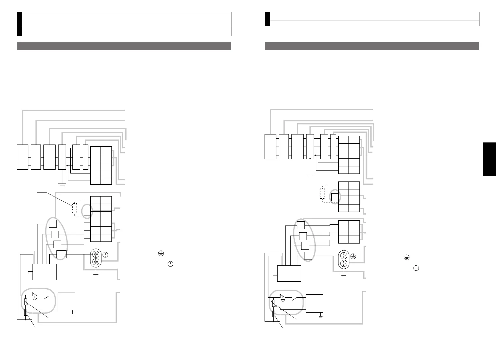
3. System Conguration and Wiring
Wiring of the Main Circuit (Connector type)
3. System Conguration and Wiring
Wiring of the Main Circuit (Connector type)
A to D-frame, 100 V / 200 V type
•Wiringshouldbeperformedbyaspecialistoranauthorizedpersonnel.
•Donotturnonthepoweruntilthewiringiscompleted.
•Nevertouchthepowerconnector(XAandXB)towhichhighvoltageisapplied.
Thereisariskofelectricshock.
• Tips on Wiring
1)Wireconnector(XAandXB).
2)Connectthewiredconnectortothedriver.
Fullyinserttheconnectortothebottomuntilitclicks.
Motor
Varistor
DC
24 V
MCCB
Power
supply
NF MC
U
V
W
E
L
Fuse (125 V 10 A)
• Check the name plate of the driver for power
specifications.
• Provide a residual current device. The residual
current device to be the one designed for
"Inverter" and is equipped with countermeasures
for harmonics.
• Provide a circuit breaker.
• Make sure to provide a noise filter.
• Provide coil surge suppression units to the coil of
the Magnetic Contactor recommended by
manufacturer.
Never start/stop the motor with this Magnetic
Contactor.
• Provide an AC Reactor.
• Connect L1 and L1C, and L3 and L2C at single
phase use (100 V and 200 V), and don't use L2.
• Match the colors of the motor lead wires to those of
the corresponding motor output terminals (U,V,W).
• Don't disconnect the shorting cable between B2 and
B3 (C and D frame type). Shorting cable is not
required for A and B frame. Disconnect this only
when the external regenerative register is used.
• Avoid shorting and grounding. Don't connect
the main power.
• Earth-ground this.
• To prevent electric shock, be sure to connect the
ground terminal ( ) of the driver, and the ground
terminal (ground plate) of the control panel.
• The ground terminal ( ) must not be shared with
other equipment.
Two ground terminals are provided.
• Don't connect the earth cable to other inserting
slot, nor make them touch.
• Compose a duplex Brake Control Circuit so that the
brake can also be activated by an external
immediate stop signal.
• The holding Brake has no polarity.
• For the capacity of the holding brake and how to
use it, refer to P.B43, "Specifications of Built-in
Holding Brake".
• Provide a varistor.
Connect a 10 A fuse in series with the varistor.
Ground resistance: 100 Ω max.
For applicable wire,
refer to P.B14.
L1C
L3
L2
L1
L2C
B1
B3
B2
U
V
W
XA
XB
2
3
4
5
1
2
3
4
5
6
1
DC power supply
for brake
External
regenerative
resistor
* These colors
are used for
optional cable.
Red
Black
Green or
Green/yellow
White
RCD
Motor
Varistor
DC
24 V
U
V
W
E
Fuse (125 V 10 A)
• Check the name plate of the driver for power
specifications.
• Provide a residual current device. The residual
current device to be the one designed for
"Inverter" and is equipped with countermeasures
for harmonics.
• Provide a circuit breaker.
• Make sure to provide a noise filter.
• Provide coil surge suppression units to the coil of
the Magnetic Contactor recommended by
manufacturer.
Never start/stop the motor with this Magnetic
Contactor.
• Provide an AC Reactor.
• Connect L1 and L1C, and L3 and L2C at single
phase use (100 V and 200 V), and don't use L2.
• Don't disconnect the shorting cable between B2 and
B3. Disconnect this only when the external
regenerative register is used.
• Do not connect anything to NC.
• Match the colors of the motor lead wires to those of
the corresponding motor output terminals (U,V,W).
• Avoid shorting and grounding. Don't connect the
main power.
• Earth-ground this.
• To prevent electric shock, be sure to connect the
ground terminal ( ) of the driver, and the ground
terminal (ground plate) of the control panel.
• The ground terminal ( ) must not be shared with
other equipment. Two ground terminals are provided.
• Don't connect the earth cable to other inserting
slot, nor make them touch.
• Compose a duplex Brake Control Circuit so that the
brake can also be activated by an external
immediate stop signal.
• The holding Brake has no polarity.
• For the capacity of the holding brake and how to use
it, refer to P.B43, "Specifications of Built-in Holding
Brake".
• Provide a varistor.
Connect a 10 A fuse in series with the varistor.
Ground resistance: 100 Ω max.
For applicable wire, refer to P.B14.
L1C
L3
L2
L1
L2C
B1
B3
NC
U
V
W
XA
XC
XB
2
3
4
5
1
2
3
1
3
B2
2
4
1
DC power supply
for brake
Red
Black
Green
White
MCCB
Power
supply
NF MC LRCD
External regenerative
resistor
* These colors
are used for
optional cable.
E-frame, 200 V type
•Wiringshouldbeperformedbyaspecialistoranauthorizedpersonnel.
•Donotturnonthepoweruntilthewiringiscompleted.
•Nevertouchthepowerconnector(XA,XBandXC)towhichhighvoltageisapplied.
Thereisariskofelectricshock.
• Tips on Wiring
1)Wireconnector(XA,XBandXC).
2)Connectthewiredconnectortothedriver.
Fullyinserttheconnectortothebottomuntilitclicks.