45
ENGLISH
On-screen display
Input switching/Signal switching
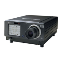
This displays the stored signal name for the STATUS screen during signal switching.
Stored signal details
RGB
INPUTNo.:1
NAME: xxx60-A5-2
ID:ALL
SIGNALSTATUS
NAME:xxx60-A5-2
MEMORY-No. :A5-2
S.S.No. :−
INPUTNo, :1
fH :48.30kHz
fV :60.00Hz
SYNC STATE :H(NEG)
V(NEG)
75ohm
SUBMEMORY :
NAMEENTRY :ENTER
EXIT :MENU
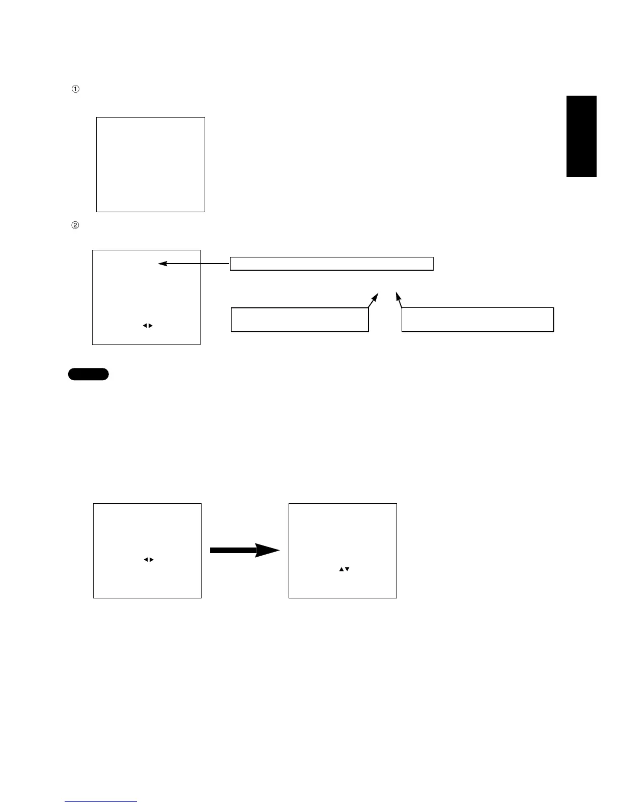
A name can be entered for each sub-memory.
MEMORY-No:A5-2
Address No. (A1,A2,....H7,H8)
Location where signal is stored
Displays sub-memory number(1-9)
1 is the basic signal.
NOTE
Restrictions
• Up to 8 sub memories can be stored for each input signal. (Therefore there are 9 types in total, including the
basic signal)
• A total of 32 sub memories can be stored in this equipment.
Sub-memory list
Input “7680” for the PASSWORD at the OPTION MENU.
This displays the list of signals stored as sub-memories.
PASSWORD
****
POSITION :
SELECT :0ー9
SET :ENTER
CANCEL :MENU
SUBMEMORYLIST
NAMEINPUT
A5-2xxx60-A5-21
A5-3xxx60-A5-31
A5-9xxx60-A5-91
〈NOENTRY〉 -
〈NOENTRY〉 -
〈NOENTRY〉 -
〈NOENTRY〉 -
〈NOENTRY〉 -
NEXTPAGE
DELETE : STD
SELECT :
STATUS :ENTER
EXIT :MENU