64
ENGLISH
When receiving 480i with analog component signal YCbCr input, it is possible to switch Cb, Cr input.
Switching procedure
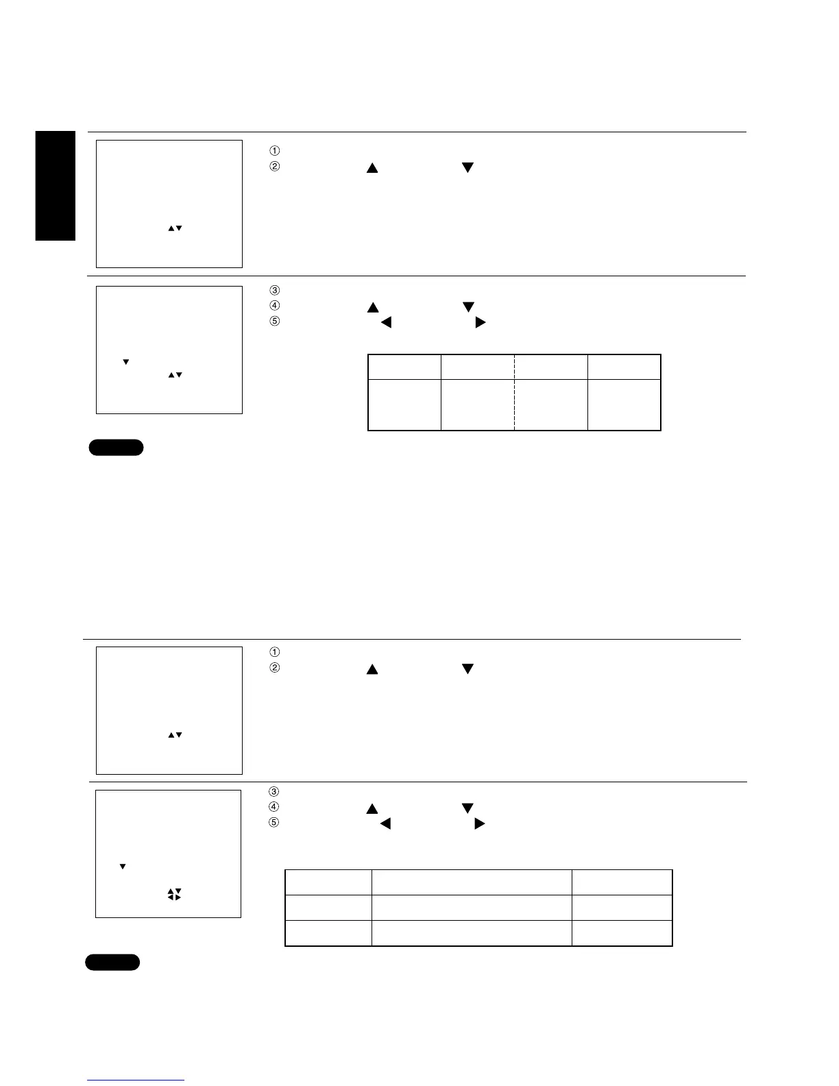
Press the MENU button. ... The MENU screen will be displayed.
Press the UP ( ) and DOWN ( ) arrow buttons to select PICTURE.
Press the ENTER button. ... The PICTURE screen will be displayed.
Press the UP ( ) and DOWN ( ) arrow buttons to select FORMAT.
Press the LEFT ( ) and RIGHT ( ) arrow buttons to switch signal format.
• Switching is done with the SMPTE and BETACAM toggle.
• This function can be used only when input is done with an analog RGB input module (ET-MD95RGB).
• This function enables switching only when receiving 480i in YCbCr mode. Switching cannot be done in
RGB REALITY mode, RGB mode, or when receiving signals other than 480i.
• The initial value is SMPTE.
When inputting BETACAM with YC
b
Cr 480i
MENU
AUTO SETUP
LENS
PICTURE
POSITION
OPTION
SIGNALLIST
TEST PATTERN
MENU :
SUBMENU : ENTER
EXIT : MENU
PICTURE
COLOR TEMP : ****
BRIGHT :nnn
CONTRAST :nnn
COLOR :nnn
TINT :nnn
SHARPNESSH :nnn
SHARPNESSV :nnn
NR :***
GAMMAMODE :2.2
MENU :
SUBMENU : ENTER
EXIT:MENU
NOTE
With analog RGB input, it is possible to switch the input impedance (signal level) of the sync signal. When
connecting with equipment (like a signal selector) whose sync output impedance is 75 ohm, use 75 ohm, and when
connection with equipment (like a PC video card) whose sync output is TTL, switch to TTL (HI-Z).
Switching procedure
Press the MENU button. ... The MENU screen will be displayed.
Press the UP ( ) and DOWN ( ) arrow buttons to select OPTION.
Press the ENTER button. ... The OPTION screen will be displayed.
Press the UP ( ) and DOWN ( ) arrow buttons to select SYNC TERM.
Press the LEFT ( ) and RIGHT ( ) arrow buttons to switch input impedance
(signal level) of sync signal.
• Switching is done using the 75 ohm and TTL (HI-Z) toggle.
• This function can be used only when input is done with an analogue RGB input module (ET-MD95RGB).
• Use by switching for each input signal.
• The initial value is 75 ohm.
• When this switching is performed, the CLOCK phase and image position may shift, so adjust again.
Method of switching input impedance(signal level)for sync input
MENU
AUTO SETUP
LENS
PICTURE
POSITION
OPTION
SIGNALLIST
TEST PATTERN
MENU :
SUBMENU : ENTER
EXIT : MENU
NOTE
SYNC TERM.
Signal Level
75 ohm
TTL(HI-Z)
Input Impedance
Amplitude:0.6 V [p-p]―4.0 V [p-p]
High level : more than 2.0 V
Loe level : Less than 0.8 V
1 kΩ
75 Ω