49
ENGLISH
Signals which cannot be adjusted automatically should be adjusted manually. The following settings can be
adjusted manually, and the respective adjustment procedures are given below.
1.Input signal resolution data
2.Clock phase
3.Picture position
Adjustment procedure
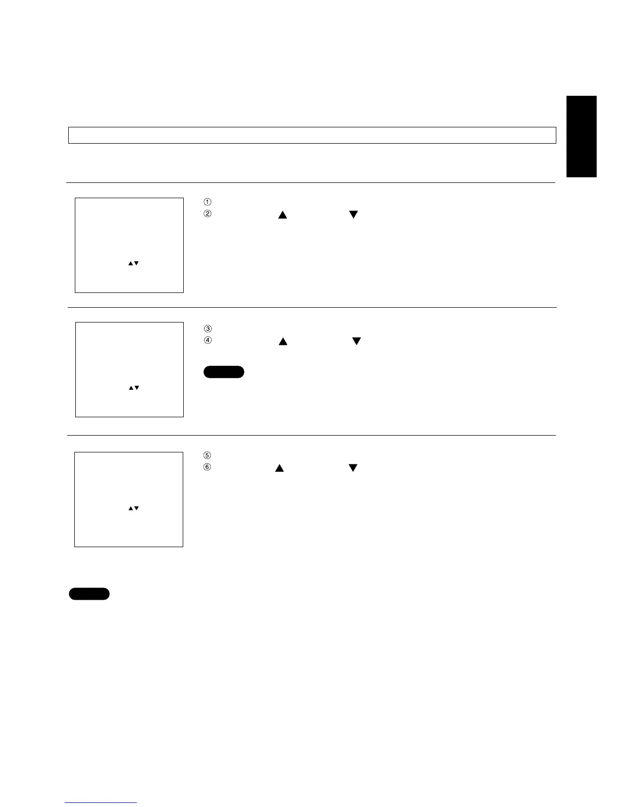
Press the MENU button. ... The MENU screen will be displayed.
Press the UP ( ) and DOWN ( ) arrow buttons to select POSITION.
Press the ENTER button. ... The POSITION screen will be displayed.
Press the UP ( ) and DOWN ( ) arrow buttons to select INPUT
RESOLUTION.
• The input resolution can be adjusted when an RGB signal has been input with
the analogue RGB module (ET-MD95RGB)
Press the ENTER button. ... The INPUT RESOLUTION screen will be displayed.
Press the UP ( ) and DOWN ( ) arrow buttons to select the desired item, and
use the control level buttons (+ and -) to adjust.
TOTAL DOTS ----- Total number of horizontal dots
DISP DOTS -------- Actually displayed number of horizontal dots
TOTAL LINES ----- Total number of vertical lines
DISP LINES -------- Actually displayed number of vertical lines
Numeric values for each item are displayed according to the input signal. If vertical stripes or chipped areas appear
on the screen, increase and decrease the displayed values to adjust the screen to its optimum state.
• The input of an all-white picture does not allow the above stripes to appear.
• The picture may become distorted during the automatic adjustment, but this is normal.
Adjusting the picture manually
INPUTRESOLUTION
TOTALDOTSnnnn
DISPDOTSnnnn
TOTALLINESnnnn
DISPLINESnnnn
DOTSCLOCKnnn.nnMHz
MENU :
ADJUST : +−
EXIT : MENU
NOTE
Adjusting the input signal resolution
MENU
AUTO SETUP
LENS
PICTURE
POSITION
OPTION
SIGNALLIST
TEST PATTERN
MENU :
SUBMENU : ENTER
EXIT : MENU
POSITION
SHIFT
SIZE
BLK
CLOCKPHASE
INPUTRESOLUTION
CLAMPPOSITION
KEYSTONE
EDGEBLENDING
MENU :
SUB MENU : ENTER
EXIT : MENU
NOTE