EasyManua.ls Logo

Panasonic PT-D9510E User Manual

Panasonic PT-D9510E
94 pages
To Next Page IconTo Next Page
Page #1 background imageLoading...
Page #1 background image
PROJECTOR
P
O
W
E
R
S
Y
S
T
E
M
S
E
L
E
C
T
O
R
S
T
D
R
G
B
I
N
P
U
T
1
I
N
P
U
T
2
I
N
P
U
T
3
BRIGHT
CONTRAST
LENS
+
P
C
-
M
U
T
E
O
N
S
C
R
E
E
N
N
E
X
T
ID SELECT
I
D
A
L
L
1
2
3
4
5
6
7
8
9
0
M
E
N
U
E
N
T
E
R
Read these instructions completely before operating this unit.
TQBJ0085
Operating Instructions
1-94
Bedienungsanleitung
95-187
DLP™ based Projector Commercial Use
Models No. PT-D9510E
PT-D9610E
Operating Instructions

Table of Contents

Question and Answer IconNeed help?

Do you have a question about the Panasonic PT-D9510E and is the answer not in the manual?

Panasonic PT-D9510E Specifications

General IconGeneral
BrandPanasonic
ModelPT-D9510E
CategoryProjector
LanguageEnglish

Summary

Product Outline

Features

IMPORTANT SAFETY NOTICE

Safety Warnings

Covers earthing, protection from rain/moisture, and servicing by qualified personnel.

Electrical Safety and Operation

Requirement for a 16A fused line connection for safe operation.

Precautions with regards to safety

Avoid installing the projector in any of the following places

Lists hazardous locations to avoid for projector installation due to vibration, moisture, or interference.

Always connect to a secure earth.

Instruction to connect an earth wire to prevent electric shocks.

When using the projector

Handling and Placement Precautions

Avoid looking into the lens, unstable placement, objects on top, foreign objects, and covering outlets.

Electrical Safety and Cable Handling

Warnings about cover removal, water spills, secure plug insertion, wet hands, and cable damage.

Emergency Procedures

Steps to take for smoke/odor issues and caution for injury hazards.

Precautions on handling

Setting-up

Dedicated power supply, avoiding vibration/shocks, and proximity to power lines.

If installing the projector to the ceiling, be sure to have a qualified technician carry out the work.

Requirement for qualified technician for ceiling installation, including bracket usage.

Cleaning and maintenance

Name and function of each part

<Projector>

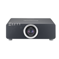
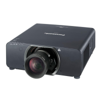
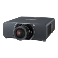
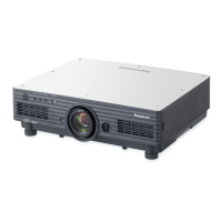
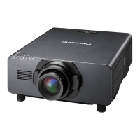
Details on projector components and connectors.

<Projector> Controls and Indicators

Explanation of buttons, indicators, and self-diagnosis.

Name and function of each remote control part

<Remote control unit> Standard & Input Buttons

Explanation of STD, SYSTEM SELECTOR, POWER, and INPUT buttons.

<Remote control unit> Adjustment & Selection Buttons

Details on CONTRAST, BRIGHT, Numeric, PIC-MUTE, ON SCREEN, NEXT, ID SELECT, ID ALL buttons.

Name and function of each remote control part (continued)

<Remote control unit> MENU, Control & Arrow Buttons

Description of MENU, Control level, and Arrow buttons for navigation and adjustment.

Before using the remote control unit

Inserting the batteries

Battery insertion and usage notes.

Using the remote control unit with the cable

Turning the power ON and OFF

Turning the power on

Procedure for turning the main power ON and then the standby power.

Turning the power off

Procedure for turning the projector from standby to main power OFF, including cooling fan operation.

On-screen menu operation guide

Before using the projector

Installing the projection lens

Procedure for installing a projection lens, including notes on handling.

Setting up the projector

Installing to the floor (Including the direct rear-mounting)

Drawing and steps for floor installation, including screen and projector placement.

Installing the projector

Steps for projector installation, setting lens height/centerline.

Installing to the ceiling (Including direct rear-projection)

Projection distance for each projection lens (sold separately)

Projection distance measurements for PT-D9510E (screen aspect ratio: 4:3)

Detailed table of projection distances for 4:3 aspect ratio with different lenses.

Projection distance measurements for PT-D9510E (screen aspect ratio: 16:9)

Projection distance measurements for PT-D9610E (screen aspect ratio: 5:4)

Projection distance measurements for PT-D9610E(screen aspect ratio: 16:9)

Calculation of the projection distance for each projection lens (for PT-D9510E)

Calculation of the projection distance for each projection lens (for PT-D9610E)

Setting the projection method

Adjusting the lens

Adjusting the focus

Guide for adjusting the lens focus using control buttons.

Adjusting the lens position (optical shift)

Instructions for adjusting the lens position (optical shift).

Installing the input module

Types of input module (sold separately)

Lists available input modules (ET-MD95RGB, ET-MD95VM2, etc.) and their signal types.

Installing the input modules

Installation procedure

Steps for removing the slot cover, fitting the module, and securing it.

Connecting the input module signal source

Connecting the signal source to the input module for analogue RGB signals

Connecting an analogue RGB signal source

Details on connecting a PC's RGB signal via D-SUB to BNC cable.

Analogue RGB signals that can be input

Connecting the signal source to the input module for video signals

Connecting a component signal source

Instructions for connecting component signals (Y, Cr, Cb) from a DVD player.

Connecting a video signal source

Instructions for connecting video signals (LINE/Y/C) from players or VCRs.

Connecting the signal source to the input module for TMDS signals

Connecting the signal source to the input module for serial digital signals

Selecting the input signal

Selecting the system format

Selecting the signal of ET-MD95VM2(sold separately)

Registering input signal data

Registration new signal

Procedure for registering a new signal via the menu.

Registration procedure

Signal registration steps, including name and memory number.

When the memory does not allow new signal registration because it is full

Overwriting registration procedure

Steps to overwrite old data with new signal registration.

Using the RGB REALITY mode

Adjusting the picture automatically

General automatic adjustment

Procedure for performing general automatic picture adjustment.

Special signal automatic adjustment

Adjusting the picture manually

Adjusting the input signal resolution

Procedure for manually adjusting input signal resolution settings.

Adjusting the clock phase

Adjusting the picture position

Adjusting the blanking

Adjusting the clamp position

Adjusting the keystone(Trapezoidal distortion)

Adjustment procedure

Step-by-step guide to adjust keystone (horizontal) and vertical linearity.

Adjusting the picture to the desired setting

Adjusting the COLOUR setting

Guide for adjusting the COLOUR setting level and related controls.

Adjusting the white balance

Adjustment procedure (Project a signal to be adjusted)

Step-by-step guide to adjust COLOR TEMP and WHITE BALANCE.

Adjusting the picture quality

Adjustment Item Details

Adjusting the picture size

Displaying a test pattern

Adjusting the edge blending

Adjusting the color matching

Adjustment procedure

Step-by-step guide to adjust COLOR MATCHING for R, G, B components.

Setting and specifying ID numbers

Setting ID numbers

Procedure for setting ID numbers (ALL or 1-64) via the OPTION menu.

Setting remote control unit ID numbers

Setting method

Procedure for setting ID number using ID SELECT, NEXT, and numeric buttons.

Using the RS-232C connectors

Set the communication parameters below

List of communication parameters (Baud rate, Parity, VPS system, etc.).

RS-232C settings

Setting procedure

Step-by-step guide to set RS-232C parameters via the menu.

Selecting the RS-422 Serial Interface

Converting the RS-232C-IN port into an RS-422-IN port

Step-by-step guide for hardware modification to enable RS-422 input.

Restoring the original RS-232C-IN port function

Procedure to revert the RS-232C-IN port back from RS-422.

Selecting the RS-422 Serial Interface (continued)

Converting the RS-232C-OUT port into an RS-422-OUT port

Hardware modification steps for RS-422 output.

Restoring the original RS-232C-OUT port function

Procedure to revert RS-232C-OUT port back from RS-422.

Using the network module

Initial setting of network module

Operating procedure

Step-by-step guide to access NETWORK MODULE SETTING via menu.

Accessing from a web browser

Step-by-step access

Steps to start browser, enter IP, username, and password.

Network setting page

Configuration of network

Interface for setting network parameters like IP address, subnet mask, and gateway.

Projector control page

Interface for controlling projector functions like power, input, and picture settings.

E-mail setting page

E-mail setting page (continue)

Firmware update page

Input update file

Procedure for inputting the firmware file name and uploading it.

Checking current and update versions

How to check versions and initiate the rewrite process.

Returning the network module settings to the factory shipment condition

Procedure

Step-by-step guide for performing the factory reset.

Replacing the lamp unit

DANGER

Warning about dangers associated with lamp replacement and advising professional service.

Lamp unit replacement period

Details on lamp life span, replacement periods, and automatic shut-off.

Warning displays

Explains warning displays for remaining lamp time (yellow and red).

Before asking for service, check the following points.

Power does not turn on.

Checks for power issues: power point, cord, MAIN POWER switch, REMOTE IN 1.

No picture appears.

Checks for picture issues: cable, signal source, mute function, signal format, Y/C selection.

The remote control unit does not work.

Checks for remote control issues: batteries, obstruction, range, REMOTE IN 1/2.

LAN connection to the unit is impossible

Checks for LAN connection issues: cable, IP address, network compatibility, browser URL.

Specifications

Input signals

Related product manuals