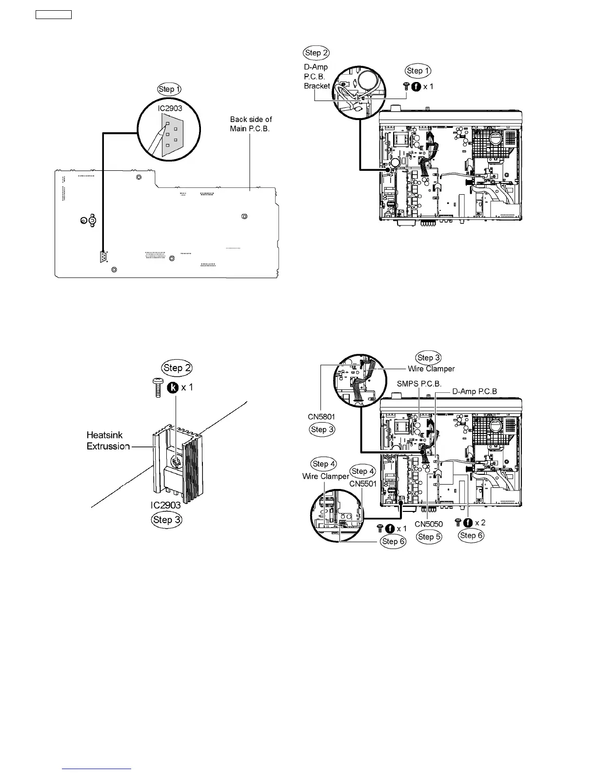
Step 1 Desolder pins of the regulator IC (IC2903) on the back
side of Main P.C.B.
Step 2 Remove 1 screw from the regulator IC (IC2903).
Step 3 Remove the regulator IC (IC2903) from the heatsink
extrussion.
Caution : Handle the heatsink extrussion with caution due to its
high temperature after prolonged use. Touching it may lead to
injuries.
Note: Refer to the diagrams of Main P.C.B. (Item 10.15) for the
location of the part.
10.17. Disassembly of D-Amp P.C.B.
·
Follow (Step 1) to (Step 3) of Item 10.3.
·
Disassembly of D-Amp P.C.B. Bracket.
Step 1 Remove 1 screw from AC-Inlet P.C.B.
Step 2 Remove the D-Amp P.C.B. bracket.
·
Disassembly of D-Amp P.C.B.
Step 3 Remove the wire clamper to detach FFC cable from the
connector (CN5801) on SMPS P.C.B.
Step 4 Remove the wire clamper to detach FFC cable from the
connector (CN5501) of fan unit on D-Amp P.C.B.
Step 5 Detach FFC cable from the connector (CN5050) on D-
Amp P.C.B.
Step 6 Remove 3 screws from D-Amp P.C.B.
Step 7 Remove 5 screws from the rear panel.
Step 8 Release the tab of the rear panel in the direction of
arrow.
Step 9 Remove D-Amp P.C.B.
46
SA-PT850EE