- 21 -
6.1 KEYSWITCH NUMBERING
Sections [049] to [056]
The Keyswitch Numbering feature allows you to
assign any hardwired-input in the system, to any of
the 8 keyswitch zones in the Digiplex Control Panel.
This feature tells the control panel where the
keyswitch is connected and which of the 8 keyswitch
zones is assigned to that keyswitch. To assign a
keyswitch connected to a hard-wired input terminal,
program the module’s serial number and the number
of the input to which the keyswitch is connected, into
the section corresponding to the desired keyswitch
zone (see figure 6.2).
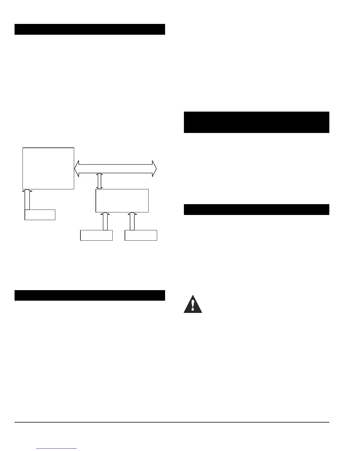
Digiplex Control Panel
SN#: 000000A2
Keyswitch B Keyswitch C
Keyswitch
Zone # Section Serial# Input#
Keyswitch A: 1 = [049] 000000A2 001
Keyswitch B: 2 = [050] 30000041 002
Keyswitch C: 3 = [051] 30000041 006
Input 2
Input 6
Figure 6.2 - Example of Keyswitch Numbering
Keyswitch A
Input 1
Input Terminals
1 2 3 4
DIGI-BUS
Zone Expander Module
SN#: 30000041
Input Terminals
1 2 3 4 5 6 7 8
6.2 KEYSWITCH DEFINITIONS
Select one of the 2 available keyswitch definitions
described below (see figure 6.1 on page 20).
6.2.1 Keyswitch Disabled
Sections [149] – [156]: First digit = 0
Disables keyswitch input.
6.2.2 Momentary Keyswitch
Sections [149] – [156]: First digit = 1
To arm a partition using the Momentary Keyswitch,
turn on the keyswitch for approximately three
seconds then turn it off. Repeating this sequence will
disarm the system. The selected Keyswitch Option
(see section 6.4) determines the type of arming.
6.2.3 Maintained Keyswitch
Sections [149] – [156]: First digit = 2
To arm a partition using the Maintained Keyswitch,
turn the switch from the “on” to the “off” position. To
disarm a partition set the keyswitch in the “on”
position. In the case of an “Arm Only” option, the
control panel will not perform any action when the
switch is in the “on” position. The selected
Keyswitch Option (see section 6.4) determines the
type of arming.
6.3 KEYSWITCH PARTITION
ASSIGNMENT
Sections [149] to [156]: Second digit = 1 to 4
The control panel provides the option of partitioning
the security system into two, three, or four
completely independent systems. Therefore, each
keyswitch must be assigned to one partition as
described in figure 6.1 on page 20. For more
information on Partitioning, refer to section 12.6.
6.4 KEYSWITCH OPTIONS
Each keyswitch zone can be programmed with one or
more of the options described below. Program the
zone options as described in figure 6.1 on page 20.
6.4.1 Arm/Disarm Option (Keyswitch)
Sections [149] to [156]:
[5] ON = Arm Only
[5] OFF = Arm & Disarm
Please note that only one of the arming
options (Stay, Force, Instant, and Regular)
can be selected.
6.4.2 Stay Arming (Keyswitch)
Sections [149] to [156]: Option [6]
Activating the keyswitch will bypass any zones
defined as Stay Zones (see section 5.4.3) in the
selected partition. All other zones will remain
activated. For more information on Stay Arming,
refer to section 14.
6.4.3 Force Arming (Keyswitch)
Sections [149] to [156]: Option [7]
Activating the keyswitch will arm the selected
partition, bypassing any open zones defined as
 Loading...