- 11 -
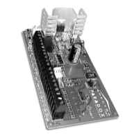
2.14 KEYSWITCH CONNECTIONS
Connect the keyswitches to the keypad, control
panel, or Zone Expander Module’s hardwired-input
terminals as shown in figure 2.8. Once a keyswitch is
connected, it must be assigned a keyswitch zone and
its parameters must be defined as described in
Keyswitch Programming (see section 6 of this
manual).
2.15 FIRE CIRCUITS
Connect the smoke detectors used in the security
system using any of the following methods. Smoke
detectors connected to the control panel or zone
expander input terminals must be assigned to a zone
in the control panel and the zone’s parameters must
be defined as a Fire Zone. For more details, refer to
Zone Programming in section 5 of this manual.
2.15.1 Standard Installation
PGM1 can be defined as a 2-wire smoke detector
input (see section 11.3); enabling smoke detectors to
be connected as shown in figure 2.12. Fire Zones
must use a 1KΩ EOL resistor. If there is a line short
or if the smoke detector becomes active, whether the
system is armed or disarmed, the control panel will
generate an alarm. If the line is open, the “Zone
Fault” trouble indication will appear in the Trouble
Display and will transmit the appropriate report code
to the central station (if programmed).
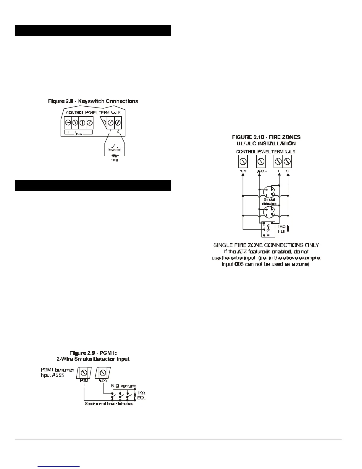
2.15.2 UL/ULC Installation
Connect the 4-wire smoke detectors and a relay as
shown in figure 2.10. In the event power is
interrupted, the relay will cause the control panel to
transmit the Global Fire Loop Trouble report if
programmed in section [697]. To reset (unlatch) the
smoke detectors after an alarm, verify that the
negative (-) of the smoke detectors are connected
to a PGM as shown in figure 2.10. Then program
the PGM with the “Smoke Reset” activation event
(see section 11.1 of this manual) to interrupt power
to the smoke detector for four seconds when the
[CLEAR] and [ENTER] keys are pressed and held for
2 seconds.
 Loading...