- 6 -
INSTALLATION
2.1 LOCATION & MOUNTING
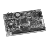
Before mounting the cabinet, push the five white nylon-
mounting studs into the back of the cabinet. Pull all
cables into the cabinet and prepare them for connection
before mounting the circuit board into the back of the
cabinet. Select an installation site that is not easily
accessible to intruders and leave at least 2” around the
panel box to permit adequate ventilation and heat
dissipation. The installation site should be dry and close
to an AC source, ground connection and telephone line
connection.
2.2 EARTH GROUND
Connect the zone and dialer ground terminals from
the control panel to the cabinet and cold water pipe
or grounding rod as per local electrical codes.
For maximum lightning protection, use
separate earth grounds for the zone and dialer
grounds as shown in figure 2.2!
2.3 AC POWER
Use a 16.5VAC (50/60Hz) transformer with a minimum
20VA rating to provide sufficient AC power. For
increased power you can use a transformer with a 40VA
rating. For UL Listed systems, you can use Amseco
Models XP-1620 or XP-1640. Do not use any switch-
controlled outlets to power the transformer. Connect the
transformer as shown in figure 2.2.
Do not connect the transformer or the back-
up battery until all wiring is completed!
2.4 BACK-UP BATTERY
In order to provide power during power loss, connect
a 12VDC 7Ah rechargeable acid/lead or gel cell back-
up battery as shown in figure 2.2. Connect the back-
up battery after applying AC power. When installing
verify proper polarity, as reversed connections will
blow the battery fuse. For information on how to set
the Battery Charge Current to either 350mA or
700mA, please refer to section 12.3 of this manual.
2.4.1 Battery Test
The control panel conducts a dynamic battery test
under load every 64 seconds. If the battery is
disconnected, if its capacity is too low or if the battery
voltage drops to 10.5 volts or less when there is no
AC, the “Battery Trouble” message will appear in the
Trouble Display (see section 14). At 8.5 volts, the
panel shuts down and all outputs close.
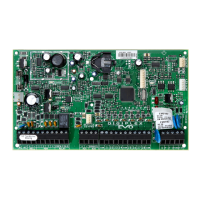
2.5 AUXILIARY POWER TERMINALS
The Digiplex Control Panel has two auxiliary
outputs. For details on available output power of
each output, please refer to figure 2.2 on the
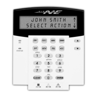
following page. You can use the auxiliary power
supply to power the motion detectors, keypads and
other accessories in your security system. A
fuseless circuit protects each auxiliary output
against current overload and automatically shuts
down if the current exceeds 1.1A. Auxiliary power
will resume once the overload condition has
restored.
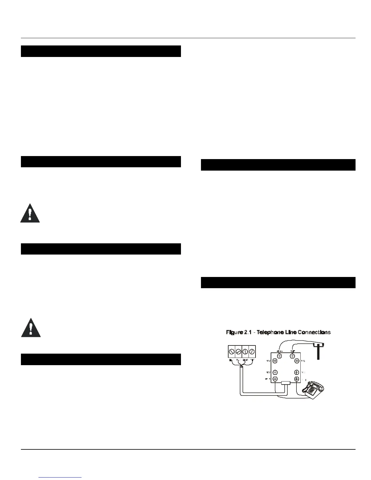
2.6 TELEPHONE LINE CONNECTION
Connect the incoming telephone company wires
into the TIP and RING connections of the control
panel. Then run the wires from T1 and R1 to the
telephone system as shown in figure 2.1.
 Loading...