61 Programming Guide
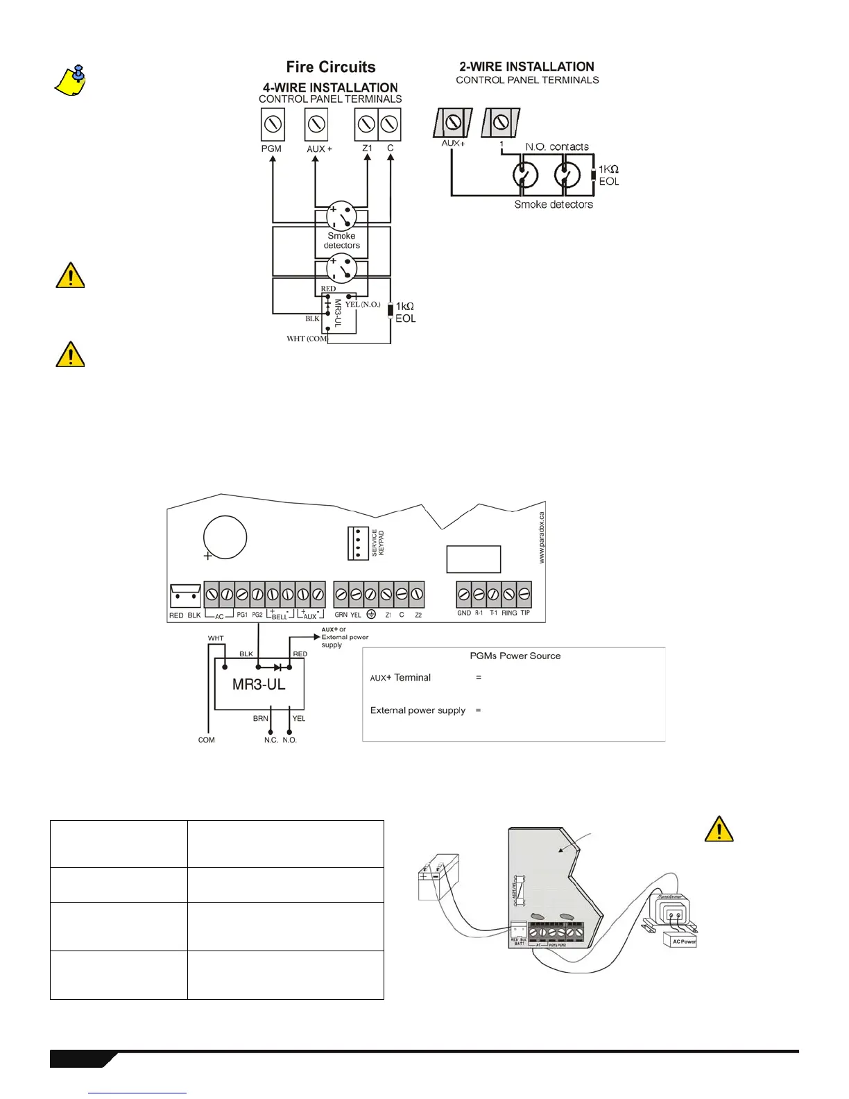
Connecting Fire Circuits
Alarm Relay and PGM Connections
AC Power & Backup Battery Connections
Transformer Requirements Table
Transformer: 16VAC 20VA* (Amseco XP-1620)
16.5VAC 40VA (Universal UB1640W)
*not verified by UL
DC Power
Supply rated at:
MG5000/MG5050 = 1.0A
SP5500/SP6000/SP7000 = 1.4A
Auxiliary Supply can
provide a maximum of:
typ: 600mA
max: 700mA
UL installations: typ. 200mA
Acceptable Battery Charge
Currents (section [700]
option [2])
350mA/700mA
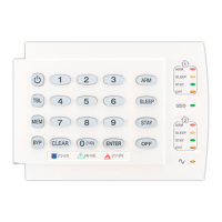
For 4-wire installation:
Program the Activation
Event so that the smoke
detectors can be reset by
pressing the [
CLEAR] +
[ENTER] keys for three
seconds. See Event Group
# 6 on page 32. For 2-wire
installation (except
SP5500): Press [
CLEAR] +
[
ENTER] to automatically
reset smoke.
It is recommended that
the smoke detectors be
connected in a daisy
chain configuration.
Each control panel
(except the SP5500)
supports a maximum of
five 2-wire smoke
detectors.
must not exceed 700mA.
PGM1 and PGM2 cannot exceed 150mA
or cannot exceed the power supply’s
current limit.
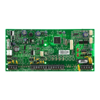
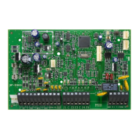
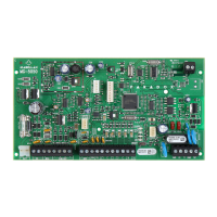
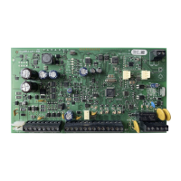
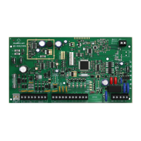
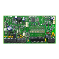
Partial view of control panel
UL Warning:
A 12Vdc / 7Ah battery is required to comply with UL fire
requirements.
Caution:
Disconnect battery before replacing the fuse.
Rechargeable Battery
UL/ULC - 12Vdc / 4Ah or 7Ah
Improper
connection
of the
transformer
may result in
damage to the
system.
 Loading...