Parker EME
Compax3 device description
192-120102 N7 - February 2004 35
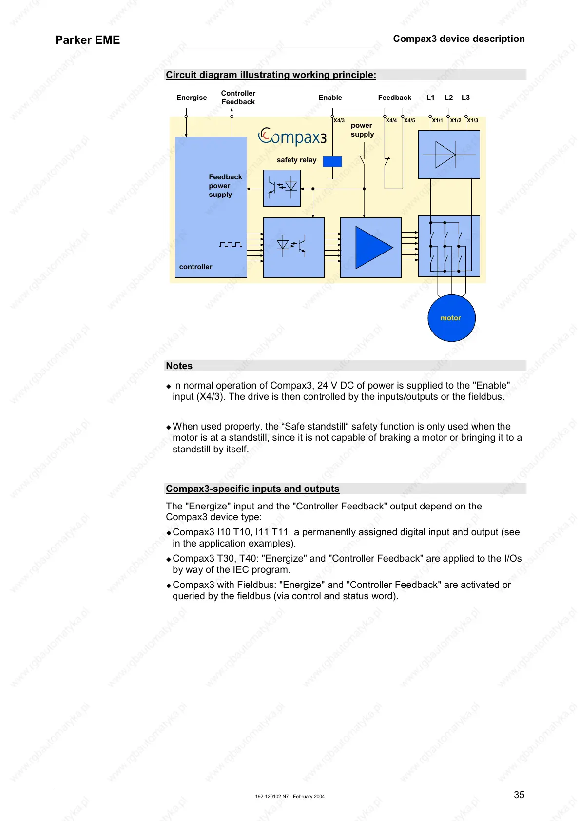
Circuit diagram illustrating working principle:
controller
motor
L1 L2 L3
Energise
Controller
Feedback
Enable Feedback
safety relay
X4/3 X4/5X4/4
X1/1 X1/2 X1/3
Feedback
power
supply
power
supply
Notes
! In normal operation of Compax3, 24 V DC of power is supplied to the "Enable"
input (X4/3). The drive is then controlled by the inputs/outputs or the fieldbus.
! When used properly, the “Safe standstill“ safety function is only used when the
motor is at a standstill, since it is not capable of braking a motor or bringing it to a
standstill by itself.
Compax3-specific inputs and outputs
The "Energize" input and the "Controller Feedback" output depend on the
Compax3 device type:
! Compax3 I10 T10, I11 T11: a permanently assigned digital input and output (see
in the application examples).
! Compax3 T30, T40: "Energize" and "Controller Feedback" are applied to the I/Os
by way of the IEC program.
! Compax3 with Fieldbus: "Energize" and "Controller Feedback" are activated or
queried by the fieldbus (via control and status word).

 Loading...


