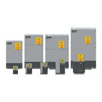
Parker Hannifin S.p.A. - Divisione S.B.C. “SPD” User’s Manual
69
10 Programming digital inputs/outputs
10.1 The pico-PLC
The internal pico-PLC is used to connect the external world (inputs/outputs) with the world of
the parameters of the drive. The PLC can be used to copy digital input to a binary parameter,
to copy a binary parameter to a digital output and to execute mathematical and Boolean
operations. The PLC program must be inserted as a list of instructions by using the keyboard
To change the instructions Pb99.13 must be set to zero. The default parameter setting
(Pb99.12) corresponds to a PLC program (see Appendix) written for a large number of
applications. In most cases it is not necessary to program the PLC itself.
The main features of the pico-PLC are:
Program steps 128
scanning time 6,144 ms
number of timers 2
number of instructions 15
stack depth 1
mathematical operations 16 / 32 bits
fast inputs 2 - (512 µs)
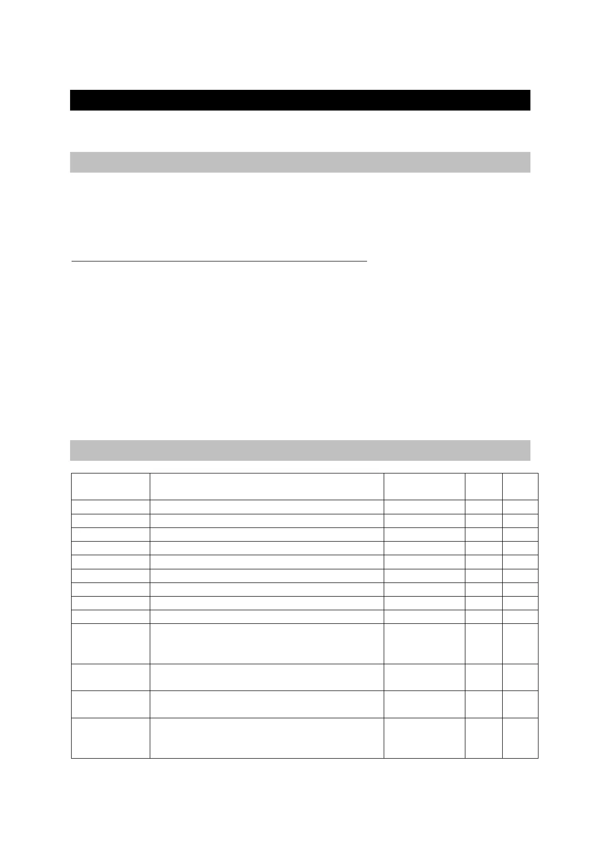
10.2 Decimal parameters PLC
Par. Description Field/Unit Def.
Type/
Notes
Pr 71 Constant value=-1 Double Word
-1 R/W
Pr 72 Constant value=0 Double Word 0
Pr 73 Constant value=1 Double Word 1
Pr 74 Constant value=2 Double Word 2
Pr 75 Constant value=10 Double Word
10
Pr76 Constant value= 100 Double Word
100
Pr 77 Constant value = 1000. Double word.
1000
Pr 78 Constant value = 1024. Double word.
1024
Pr 79 Constant value = 4096. Double word.
4096
Pr 80÷89
Free parameters.
Parameters that can be stored and
available to the user (word).
+/-32767 0 R/W
M
Pr 92 First timer of the PLC , if equal to zero,
Pb99.0=1.
0÷32767 0 R/W
Pr 93 Second timer of the PLC , if equal to
zero Pb99.1=1.
0÷32767
0 R/W
Pr151÷Pr163
Free parameters.
Parameters that can be stored and
available to the user (word).
+/-32767
0 R/W
M