Parker Hannifin S.p.A. - Divisione S.B.C. “SPD” User’s Manual
84
14.1 Description of the fields in real time mode
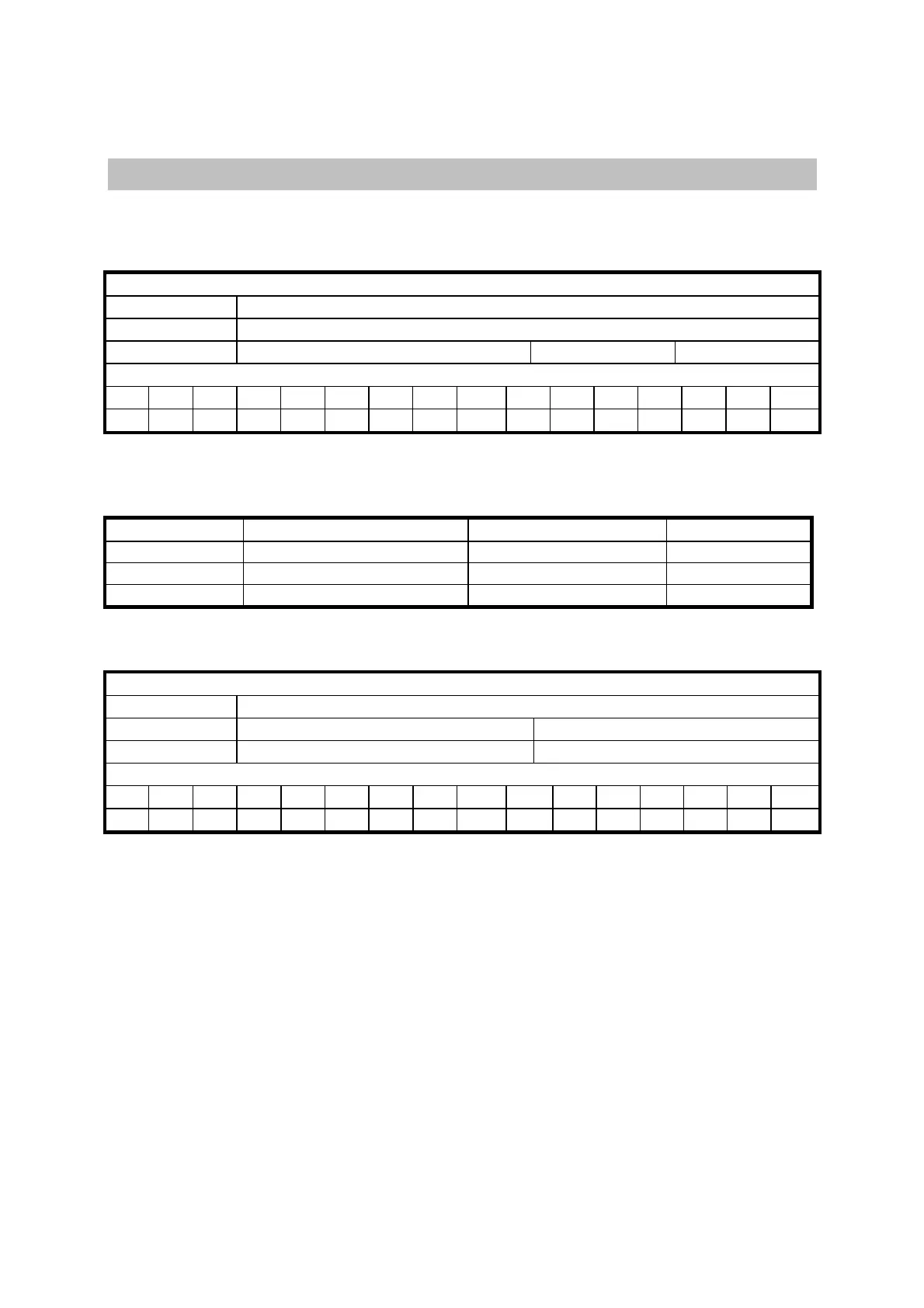
Cyclic message from the master to the SPD
Cyclic data
Data length
8 bytes
Field Name
Data
Contents
position ref. bits speed ref. bits Pr102
Identifier
ID2 ID1 ID0 - - - - - ID10 ID9 ID8 ID7 ID6 ID5 ID4 ID3
A2 A1 A0 X X X X X 0 0 0 0 0 1 1 A3
A0:A3 SPD slave address (Pr27+1), valid values 1..15.
Pr102 is used as a command and must be managed by the pico-PLC.
The received data are interpreted as follows, based on the message length:
Data length
8 Position reference (4 byte) Speed reference (2 byte) Pr102 (2 byte)
6
Position reference (4 byte) Pr102 (2 byte)
4 Speed reference (2 byte) Pr102 (2 byte)
Synchronism message from the mast to the SPD
Synchronism message
Data length
3 bytes
Field Name
Sync no meaning
Contents
Sync type 8 bits no meaning 16 bits
Identifier
ID2 ID1 ID0 - - - - - ID10 ID9 ID8 ID7 ID6 ID5 ID4 ID3
0 0 0 X X X X X 0 0 0 0 0 0 0 0
Type 0 synchronism (Sync = 0): every SPD activates the speed references and the position
references and stores the actual position of the motor
; if b150.2=1 the drive answers with a “cyclic
reply”.
Type 1 synchronism (Sync = 1): stores the actual position of the motor
; if b150.6=1 the drive
answer with a “cyclic reply”.