Parker Hannifin S.p.A. - Divisione S.B.C. “SPD” User’s Manual
78
13 SERIAL INTERFACE
The serial communication of the converter is half-duplex, master-slave, using an
asynchronous RS-485/RS-422 line. The converters take control of the line only if interrogated
by the master.
The same serial line can be connected to up to 32 converters by setting a different serial
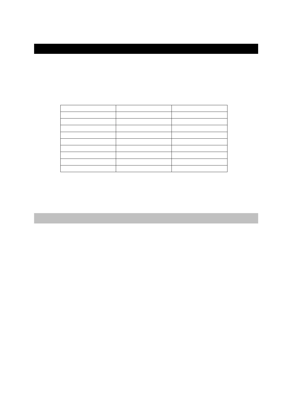
address in each to the Pr27 parameter. It is also possible to set the transmission speed by using
the Pr26 parameter as specified in the table below:
(*) The version with code Pr26=4 differs from Pr26=5 for the delay of the response of 25 ms.
This version has been developed to interface with the PLCs that require such a feature.
For the connection diagrams, see the section, Connecting the serial line.
13.1 Communication protocol
The column on the right in the table above shows the time-out value expressed in
milliseconds for each communication speed. This is the time within which the message must
be sent, beginning from the start of each message (STX). If a message is interrupted after this
time, the converter ignores what has been received and waits for the beginning of a new
message. The message consists of several consecutive bits. The format of the bits is the
following:
1 start bit
8 bit of data defined by a following byte enclosed within brackets
1 parity bit (even)
1 stop bit
The structure of the message is the following:
[STX] [CMD+ADDR] [BK+LUN] [PAR] [D0]... [Dn] [CHK]
where:
[STX] = $7E indicator of transmission start. If a field in the message different from STX
assumes the value $7E, this field is followed by a 0 ($00) so that it will not be interpreted as
an [STX].
[CMD+ADDRESS] = command and address of the device. This data is composed in the
following way: the first 5 bits (bits 0-4) define the address of the converter (from 0 to 31);
the remaining 3 bits (bits 5-7) define the type of message sent, as described in the following
table:
Pr26 (decimal base) b/s time-out (ms)
0 600 512
1 1200 256
2 2400 128
3 4800 64
4 9600 (*) 32
5 9600 32
6 19200 16
7 38400 12
8 57600 8