Parker Hannifin S.p.A. - Divisione S.B.C. “SPD” User’s Manual
88
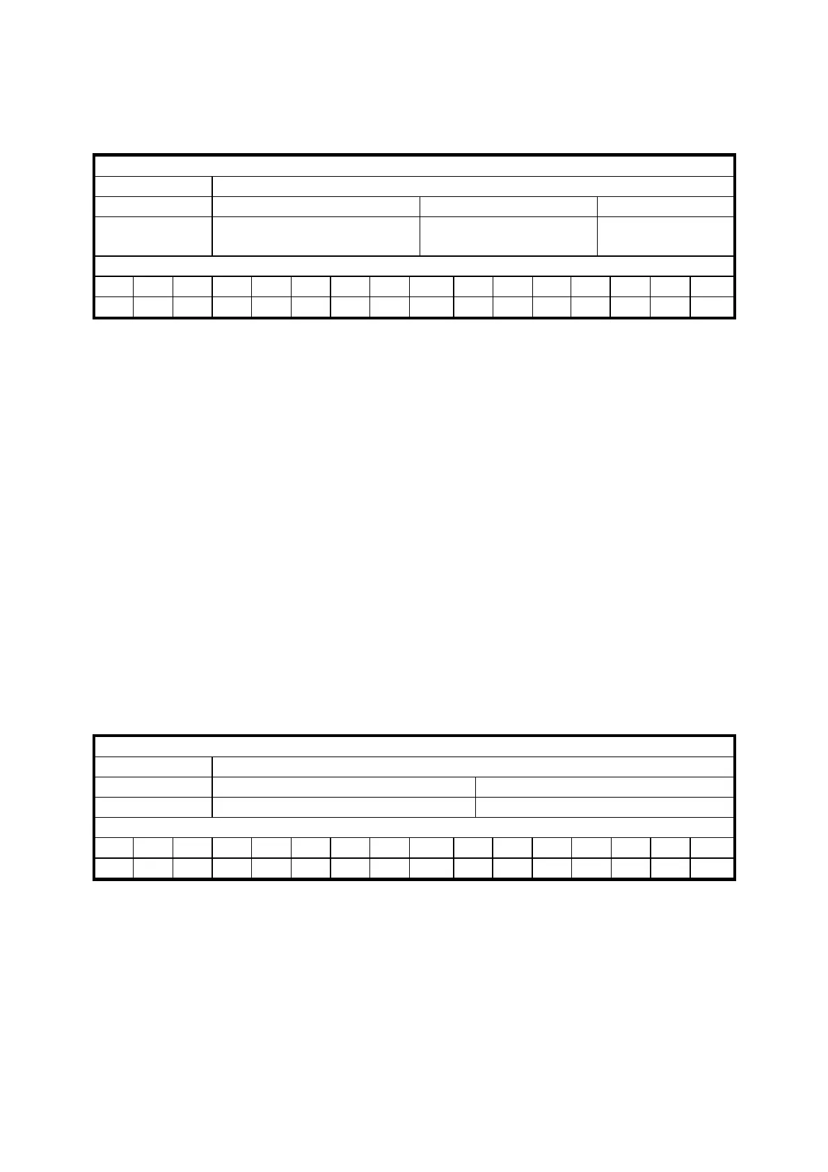
Broadcast write parameter message from the master to the SPD
Broadcast data write
Data length
7 bytes
Field Name
Cmd & Len Data Address Data
Contents
5 bit command and 3 bit
length
16 bit data address 32 bit data
Identifier
ID2 ID1 ID0 - - - - - ID10 ID9 ID8 ID7 ID6 ID5 ID4 ID3
1 1 1 X X X X X 0 0 1 0 0 0 1 1
Cmd & Len Sub-field Value Meaning
Cmd [0..4] 0 Not used
1 Write
2 SET bit Pr = Pr .OR. Data
3 RESET bit Pr = Pr .AND.
(.NOT.Data)
4 TOGGLE bit Pr = Pr .XOR. Data
5 – 31 Not used
Len [5..7] 0- 4 Number of significant bytes in the data field
Data Address
This is the address of the parameter interested in the operation (parameter number * 2 ).
The PLC instructions have the address from 8192 up to 8447.
Data
If the parameter is to be written, it contains the value of the parameter.
If one or more bits are modified, it contains the mask of the bits to be modified.
If plc programme is written, it contains the instruction code (see the section Serial interface).
Alarm message from the SPD to the master
Error
Data length
3 bytes
Field Name
Address Error
Contents
Pr27+1 Pr23
Identifier
ID2 ID1 ID0 - - - - - ID10 ID9 ID8 ID7 ID6 ID5 ID4 ID3
A2 A1 A0 X X X X X 0 0 0 1 0 0 0 A3
A0:A3 SPD slave address (Pr27+1), valid values 1..15.
If the converter is in the alarm status, it will send this message on the bus (alarm 0 = no
alarm).