17 MIC 1161 Manual
Input Connections 2.3
In general, all wiring connections are made to the instrument after it is in-
stalled. Avoid electrical shock. AC power wiring must not be connected to
the source distribution panel until all wiring connection procedures are
completed.
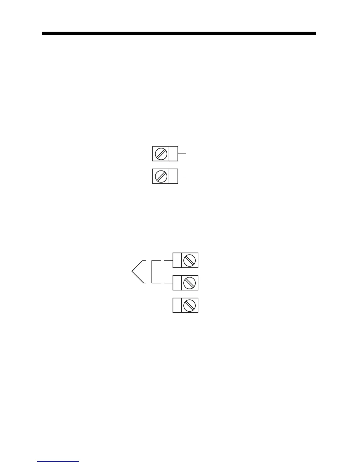
FIGURE 2-7
AC Power
Connect the line voltage, hot and neutral, to terminals 9 and 10 respectively
as illustrated below.
FIGURE 2-8
Thermocouple (T/C) Input
Make thermocouple connections as illustrated below. Connect the positive
leg of the thermocouple to terminal 5 and the negative leg to terminal 4.
FIGURE 2-9
RTD Input
Make RTD connections as illustrated on page 18. For a three wire RTD,
connect the resistive leg of the RTD to terminal 6 and the common legs to
terminals 4 and 5. For a two wire RTD, connect one leg to terminal 5 and
the other leg to terminal 6 as shown. A jumper wire supplied by the cus-
tomer must be installed between terminals 4 and 5. Input conditioning
jumper must be positioned correctly (see Appendix B) and Hardware Defini-
tion Code must be correct (see Appendix C).
9
10
L
N
4
5
6
-
+
Thermocouple
www.GlobalTestSupply.com
Find Quality Products Online at: sales@GlobalTestSupply.com


 To Next Page