MIC 1161 Manual
18
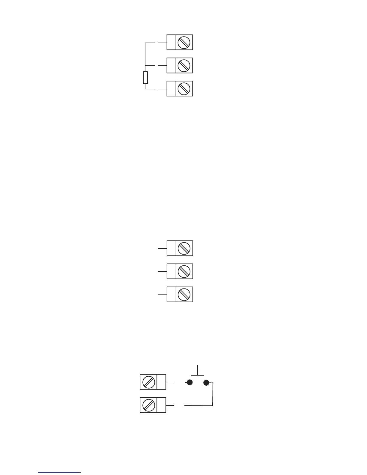
FIGURE 2-10
Volt, mV Input
Make volt and millivolt connections as shown below. Terminal 5 is positive
and terminal 4 is negative. Input conditioning jumper must be positioned
correctly (see Appendix B) and Hardware Definition Code must be correct
(see Appendix C).
mADC Input
Make mADC connections as shown below. Terminal 4 is positive and ter-
minal 6 is negative. Input conditioning jumper must be positioned correctly
(see Appendix B) and Hardware Definition Code must be correct (see Ap-
pendix C).
FIGURE 2-11
Remote Reset
Make connections as shown below.
4
5
6
RTD
4
5
6
-
+
Linear (V/mV)
+
-
Linear (mA)
11
12
N.O.
www.GlobalTestSupply.com
Find Quality Products Online at: sales@GlobalTestSupply.com
 Loading...


