Home
Partner
Touch terminals
SP-600-A
Page 71 (I;O Shield)
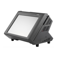
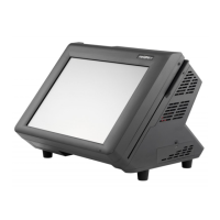
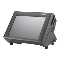
Partner SP-600-A - I;O Shield
80 pages
Manual
Save Page as PDF
To Next Page
To Next Page
To Previous Page
To Previous Page
Loading...
63
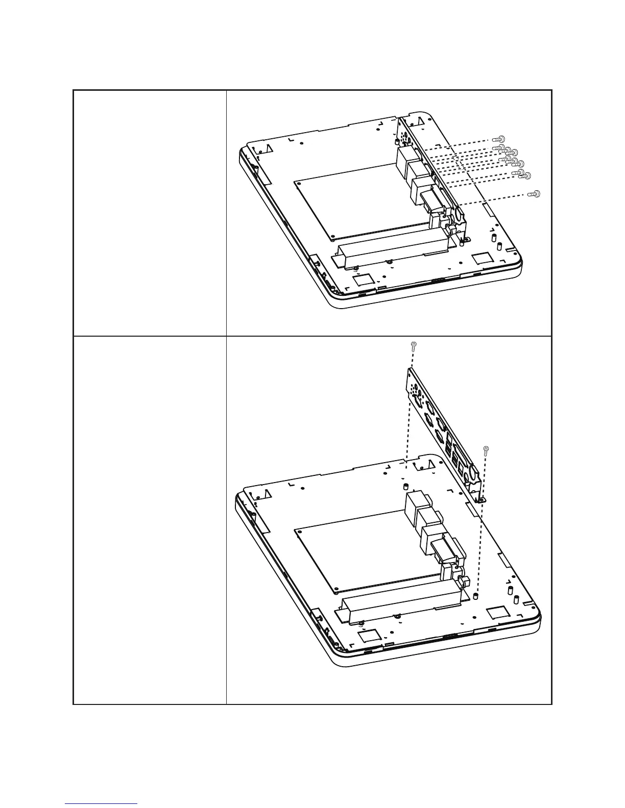
I/O Shield
Before proceeding, remove the
following FRUs.
•
“SP-600-A
Panel” on page
57.
•
“Panel Back Cover” on page
58.
1.
Remove all screws from the
I/O ports.
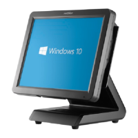
2.
Remove two screws from the
I/O shield.
3.
Remove the I/O shield.
70
72
Table of Contents
Main Page
Default Chapter
3
About this Manual
3
Revision History
3
Legislation and Weee Symbol
4
Table of Contents
5
Chapter 1 Getting Started
9
Unpacking the Machine
9
Figure 1.1 Unpacking the Machine
9
Identifying Components
10
Figure 1.2 Front-Right View
10
Figure 1.3 Rear View
11
Figure 1.4 SP-600-A I/O Connectors
12
Connector Pin Define
13
Chapter 2 Bios Setup
17
About the Setup Utility
17
Entering the Setup Utility
18
BIOS Navigation Keys
18
Figure 2.1 Main BIOS Screen
18
Using BIOS
19
Main Screen
20
Figure 2.2 Main Screen
20
Advanced Settings
21
Figure 2.3 Advanced Settings Screen
21
ACPI Settings
22
Figure 2.4 ACPI Settings Sub-Menu
22
CPU Configuration
23
Figure 2.5 CPU Configuration Sub-Menu
23
Figure 2.6 SATA Configuration Sub-Menu
24
SATA Configuration
24
Figure 2.7 USB Configuration Sub-Menu
25
USB Configuration
25
Figure 2.8 Super IO Configuration Sub-Menu
26
Super IO Configuration
26
Figure 2.9 Serial Port X Configuration Sub-Menu
27
Serial Port X Configuration
27
Figure 2.10 Parallel Port Configuration Sub-Menu
28
Parallel Port Configuration
28
Figure 2.11 Serial Port X Voltage Select Sub-Menu
29
Serial Port X Voltage Select
29
Figure 2.12 Hardware Monitor Sub-Menu
30
Hardware Monitor
30
CPU PPM Configuration
31
Figure 2.13 CPU PPM Configuration Sub-Menu
31
Chipset Settings
32
Figure 2.14 Chipset Settings Screen
32
Figure 2.15 Graphics Configuration Sub-Menu
33
Host Bridge > Graphics Configuration
33
Figure 2.16 South Bridge Sub-Menu
34
South Bridge
34
Figure 2.17 USB Configuration Sub-Menu
35
USB Configuration
35
Boot Settings
36
Figure 2.18 Boot Settings Screen
36
Security Settings
37
Figure 2.19 Security Settings Screen
37
Save & Exit
38
Figure 2.20 Save & Exit Screen
38
Chapter 3 Installing Drivers and Software
39
Driver Auto Installation
39
Intel Chipset Driver
40
Intel Chipset Graphics Driver
42
LAN Driver
44
Touch Screen Driver
46
Calibrating the Touchscreen
51
Chapter 4 Locating the Problem
53
General Checkout Guidelines
53
Cash Drawer Checkout
53
LCD Symptoms
54
Figure 4.1 Connecting a Cash Drawer
54
Touch Screen Symptoms
55
Power Symptoms
55
Network Symptoms
55
USB Symptoms
56
Peripheral-Device Symptoms
56
Boot Symptoms
56
Mainboard Jumper
57
Figure 4.2 SP-600-A Mainboard Jumper
57
Mainboard Connectors
59
Inverter Connectors
59
Figure 4.3 SP-600-A Mainboard Connectors
59
Figure 4.4 Inverter Connectors
59
CHAPTER 5 REPLACING FIELD REPLACEABLE UNITS (Frus)
61
Safety and Precautions
61
Before You Begin
62
Replacing Parts
62
Msr
63
Customer Display
63
Hdd
64
SP-600-A Panel
65
Panel Back Cover
66
Speaker
67
Power Button
68
Heatsink
69
Memory
70
Battery
70
I/O Shield
71
Mainboard Board
72
Ipanel Bracket
73
Touch Panel, LCD Panel
73
Appendix Part List and Specification
75
Figure 6.1 Exploded Diagram Main Parts
75
Part List for SP-600-A
76
Figure 6.2 Exploded Peripheral Parts
77
Part List for Peripherals
78
Specifications
79
Related product manuals
Partner SP-630-Q
73 pages
Partner SP-820
50 pages
Partner SP-850
2 pages
Partner SP-800
70 pages
Partner SP-550
2 pages
Partner SP-1060
2 pages
Partner SP-1030
80 pages
Partner SP-1000-C
46 pages
Partner SP-1000-BZ
50 pages
Partner PT-6212
72 pages
Partner PT-6215-ES
2 pages
Partner PT-6212-EB
2 pages