Copyright © 2014 PAYTER
BV. All rights reserved. No
part of this document may be
reproduced in any form by
print, photo print, microfilm,
electronic copy or any other
means without written
permission by Payter BV.
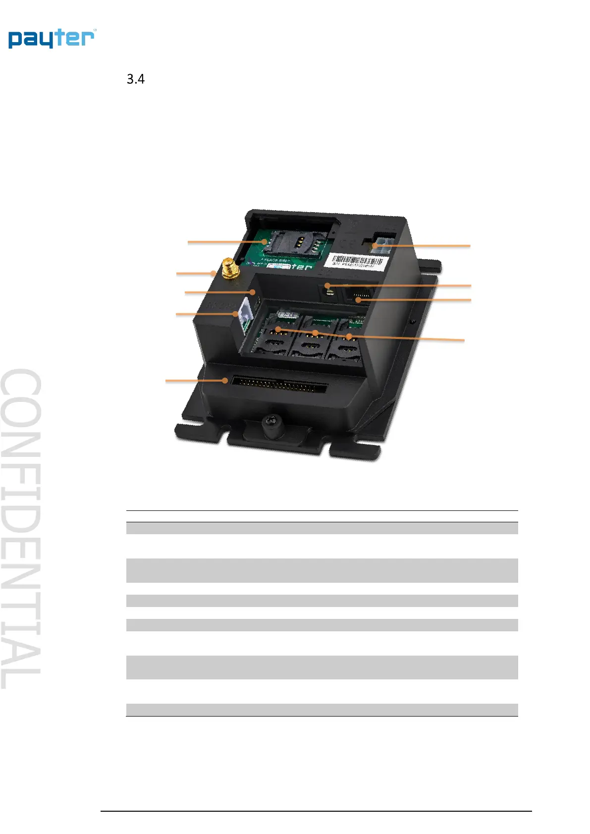
Rear view
This Part of the casing is similar for P68 & P66
Fig. 3 – Rear View
The Modem is placed behind a hatch
labeled MODEM
Antenna Connector
(SMA-Female)
Connect a suitable 3G/HSPA BAND
antenna to this connector.
Power Supply Adapter connection.
Host Machine Interface and/or Internet
connection.
The SAM slots are located behind a
Hatch labeled SAM MODULES.
Ribbon Cable connector
(Split units only)
To connect the Card Reader front unit in
the P66 Split configuration
Table 3 – Rear view item description



 To Next Page