Copyright © 2014 PAYTER
BV. All rights reserved. No
part of this document may be
reproduced in any form by
print, photo print, microfilm,
electronic copy or any other
means without written
permission by Payter BV.
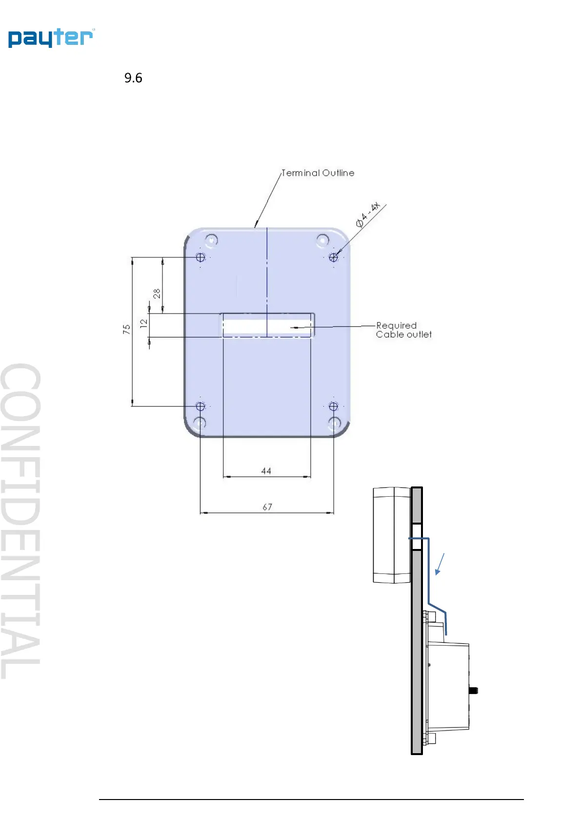
Installation P66 Split
P66S is identical to the P66 terminal with the exception that the card reader and the
communication is split into two parts. The card reader can be mounted on top of any machine,
while the communication unit is located inside the machine. The card reader can be mounted
securing four M4 screws through the machine using the below outline. An addition opening need
to be created for the ribbon cable connection to the communication unit.
Ribbon Cable
(Max. Length 585 mm)
The communication unit can be mounted using
the EVA dimensions for securing the unit.