INTELLICHEM
®
Controller Installation and User’s Guide
38
The Flow Switch is a Dry Contact Only (No Current). This Flow
Switch should only be used with the IntelliChem
®
Controller. Use
of this Flow Switch with any other brand of controller will void the
warranty and UL listing.
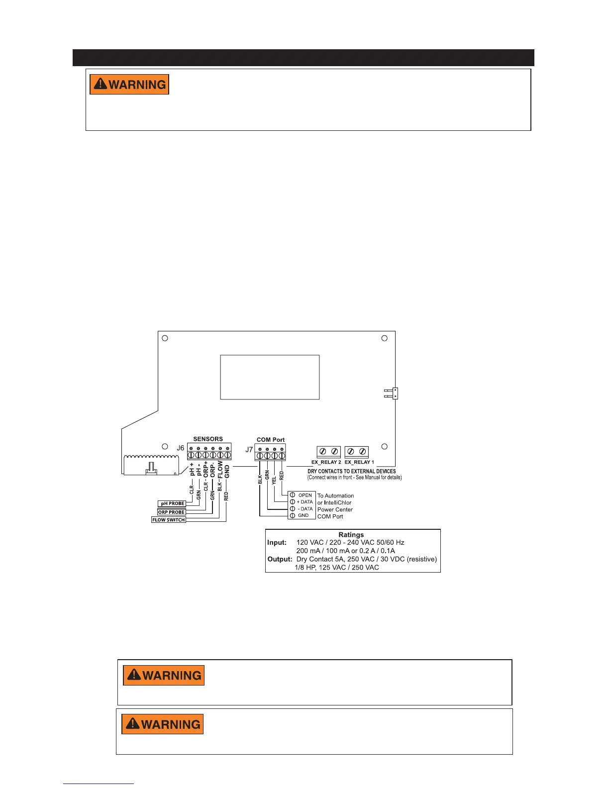
1. Route the Flow Cell switch wires into the IntelliChem controller enclosure
through the strain relief and connect the wires to J6 Sensor terminal
connector on the IntelliChem controller circuit board. Connect the
BLACK wire to the GND screw terminal and the RED wire to the
FLOW screw terminal.
2. Route the pH and ORP sensor wires into the IntelliChem controller
enclosure through the strain relief and connect to J6 Sensor terminal
connector on the IntelliChem controller circuit board. The sensor wires are
labeled. PLUS AND MINUS POLARITY MUST BE OBSERVED.
pH sensor wire: Connect the GREEN to the pH - screw terminal and the
CLEAR wire to the pH + screw terminal.
ORP sensor wire: Connect the GREEN to the ORP - screw terminal and
the CLEAR wire to the ORP + screw terminal.
Connecting the Sensors Wires to IntelliChem
®
Controller Circuit Board
Make sure that all pumps are off before drilling into any
pipe.
Never turn chemical feed pumps on when either flow cell
valve is closed.
Figure 2: IntelliChem
®
Controller J6/J7 Circuit Board Wiring
3. Turn the main pump on and open the valves to test for leaks and the free
movement of magnet. Magnet must be all the way up in order to close the
flow switch. 1/4 GPM will push the magnet all the way up.

 Loading...