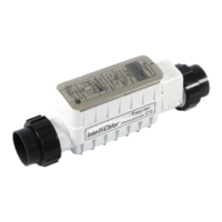
Power Center
The Power Center converts AC electrical current to a low voltage DC current which is required by the cell to
perform the electrolysis. The power supply is connected with the pool circulation pump electrical source so
that the electrolytic cell only operates when the pool pump is on. The enclosure can be mounted vertically on
the wall up to 4.57 Meters (15 feet) away from the cell controller. The Power Center contains the transformer
fuse, connector to the cell and the 110 VAC and 220 VAC wiring configuration with the 36 VDC output cable
to the cell controller. A fuse holder is mounted on the bottom of this enclosure for additional protection. There
are no other controls or lights on the unit. For more information about the Power Center, see the “IntelliChlor
Power Center Installation Guide,” (P/N 520590).
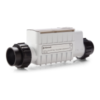
Power Center (Model PC 100)
System Diagram
The following diagram shows the IntelliChlor system functionality. It is recommended to install a 5.08 cm (2”)
check valve between the input side of the IntelliChlor cell and the main heater output pipe.
 Loading...