26
IntelliTouch ScreenLogic User’s Guide
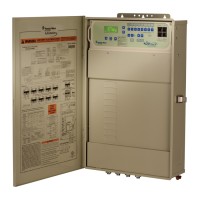
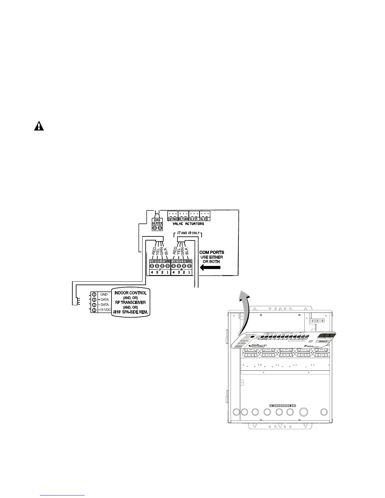
7. Strip back the cable conductors ¼ in. Insert the four wires into the screw terminals on either COM PORTS
(J7 or J8) plug located on the left side of the Personality board. Secure the wires with the four screws. Make
sure to match the color coding of the wires: The pin numbers and wire color codes are:
1 BLK = Ground
2 GRN = -DT
3 YEL = +DT
4 RED = +15 VDC
Note: Multiple wires may be inserted into a single screw terminal.
CAUTION Do NOT short GND or +15 VDC connections (Red or Black) to data lines (Green or Yellow).
The Personality board may be permanently damaged. Do NOT reverse GND or +15V or system will not operate.
8. Install the cover-panel and secure with the two retaining screws.
9. Close the hinged Outdoor Control Panel and secure with the two access screws.
10. Close the front door of the Load Center. Fasten the spring latches.
BLK
GRN
YEL
RED
Personality board
(Connector J7 or J8)