460906 Rev. D 8/2020 MASTERTEMP
125 Pool and Spa Heater Installation and User’s Guide
39
Section 1. Installation Instructions
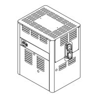
COMMUNICATION PORTS A & B
14 VDC, 2.0A Max. Combined.
Connecting IntelliFlo
®
Pump to IntelliCenter™ Control System COM PORT:
Strip 1/4” insulation from the green and yellow wire conductors.
• Connect the Green wire to pin 2 on Connector J4 or J5.
• Connect the Yellow wire to pin 3 on Connector J4 or J5.
Note: Multiple wires may be inserted into a single terminal.
Optional: COM PORT expansion module (P/N 520818) with 3 extra
COM PORTS up to 2 modules can be installed.
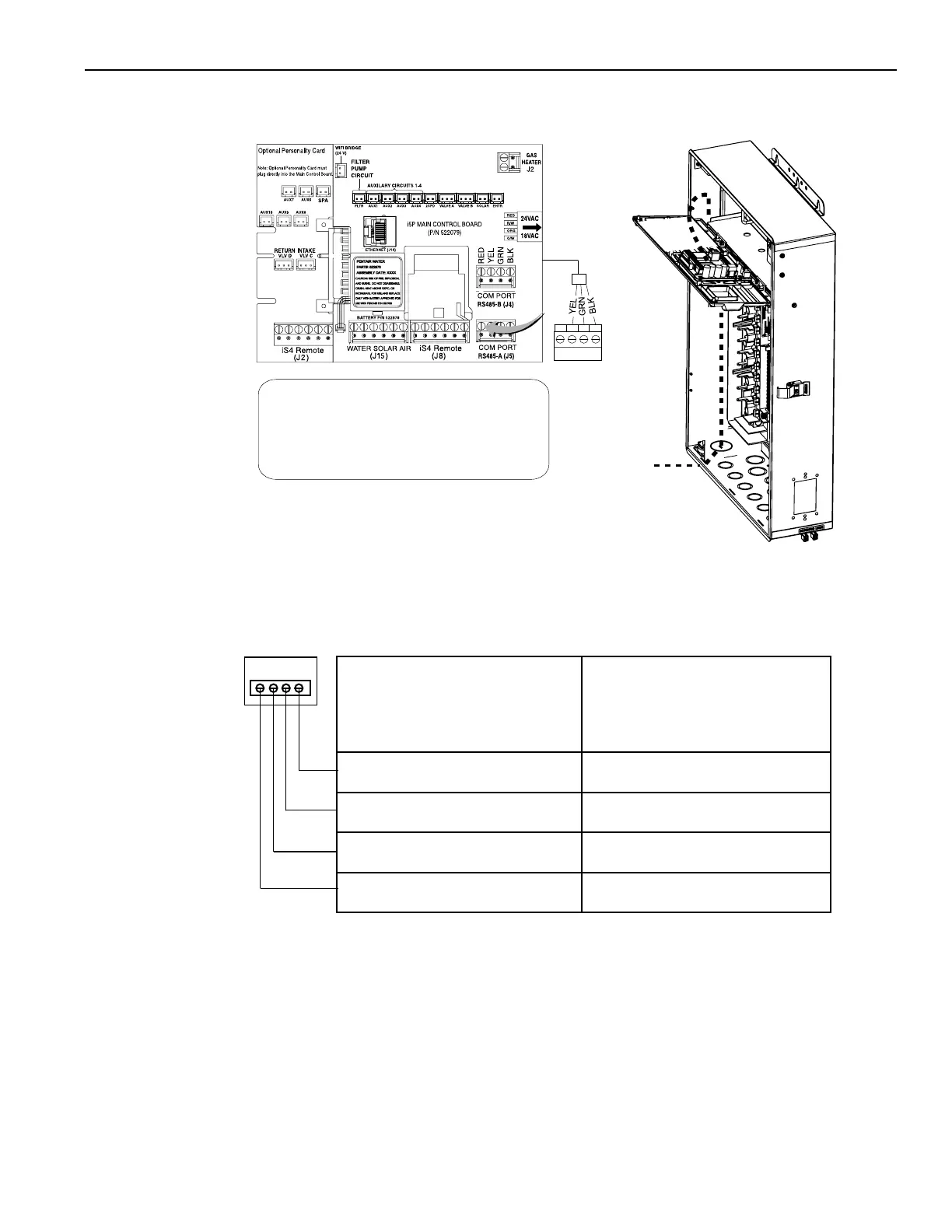
Note: COM PORT A& B
14 VDC, 2.0A Max.
Combined
4 3 2 1
+15 +DT -DT GND
TO HEATER
CONTROL PANEL
RS-485 COM PORT
Figure 36.
Connecting the RS-485 Cable from the Heater to the Load Center (Continued)
8. Reinstall the High Voltage Panel: Insert the panel’s three tabs into the lower slots on the enclosure.
9. Secure the panel with the two (2) retaining screws. Close the front door and secure with the latch. See Figure 33 on
page 37.
10. SWITCHONACpower to the IntelliCenter Control System Load Center.
MasterTemp COM Pport
Control Panel
Screw Terminal
MasterTemp Heater
COM Port
screw terminal
connector
IntelliCenter Control System
COM Port (J4 or J5)
NOT USED NOT USED
3 (YELLOW) 3 (YELLOW)
2 (GREEN) 2 (GREEN)
1 (BLACK) 1 (BLACK)
1 2 3 4
Heater to IntelliCenter wires pin assignment