Explorer Mini
Specifications - Wiring diagram
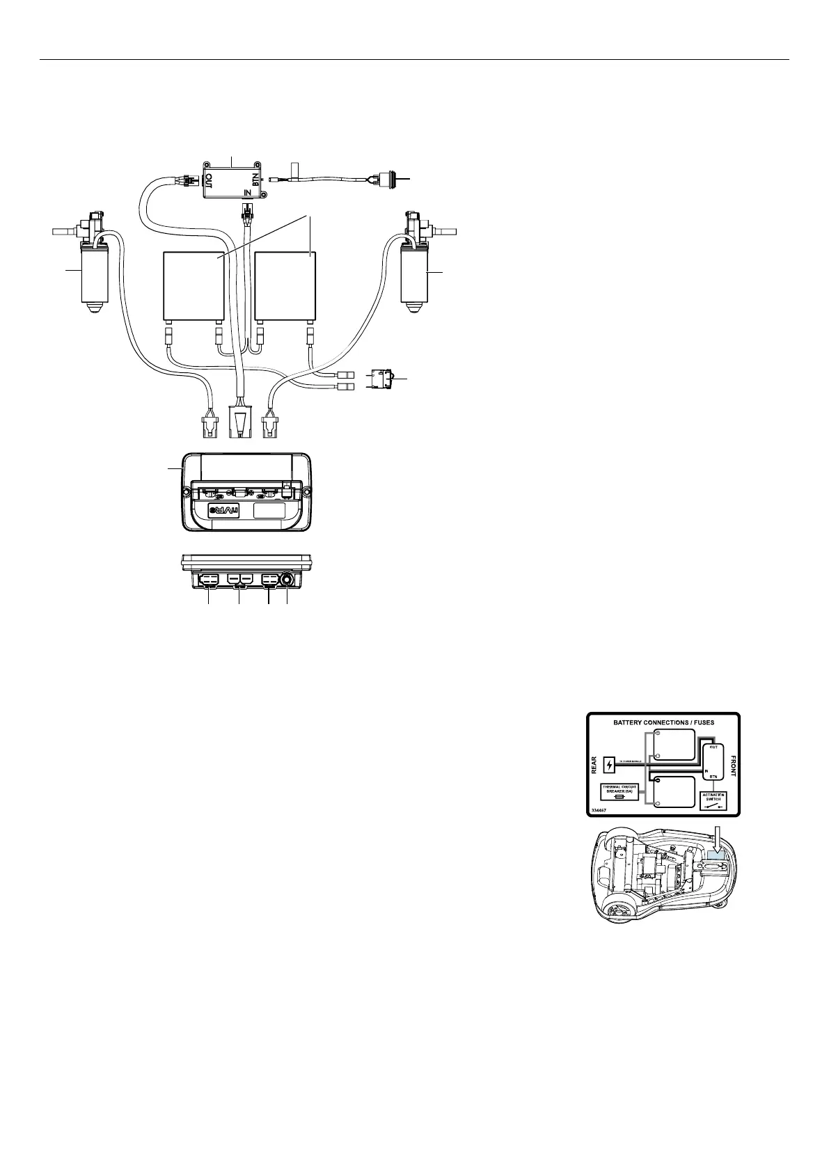
3.2 Wiring diagram
3.2.1 Base module
Figure 2. Wiring diagram for the electronics in the base module.
A. Battery saving module
B. Drive unit, left
C. nVR2 power module
D. Contact to the left drive unit
E. 24 V input
F. Contact to the right drive unit
G. Contact to the control panel
H. Main circuit breaker
I. Drive unit, right
J. Batteries
K. Start button
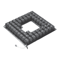
3.2.2 Batteries
Figure 3. Wiring diagram for the batteries and position
of the wiring diagram for the batteries.
The wiring diagram for the batteries is positioned at the bottom cover
of the base module.
13