24
Setting-
24.0.1
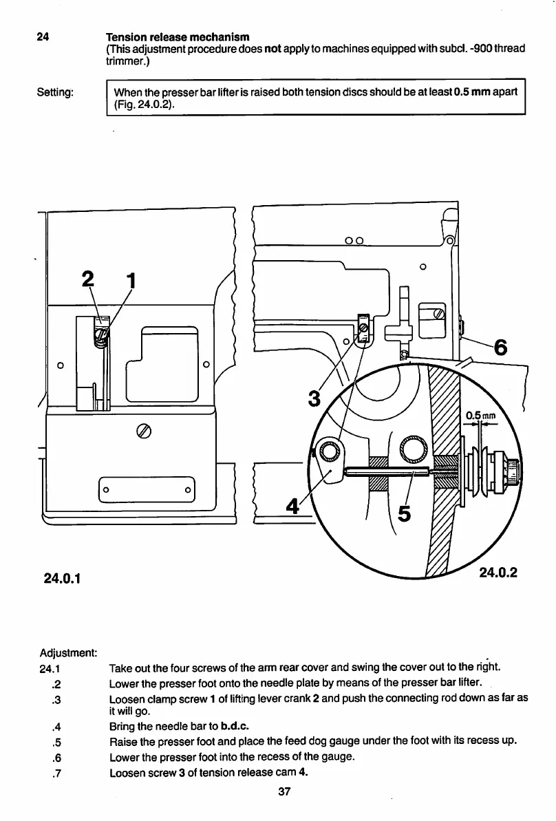
Tension
release
mechanism
(Thisadjustment procedure
does
not
applyto machines equipped withsubcl. -900 thread
trimmer.)
When the presserbar lifteris raised both tension discs should be at least0.5 mm apart
(Fig. 24.0.2).
Q)
24.0.2
Adjustment:
24.1 Take out
the
four
screws
of the arm
rear
cover
and
swing the
cover
out to
the
right.
.2 Lowerthe presser footontothe needle plate bymeans ofthe presser bar
lifter.
.3 Loosenclampscrew1 of
lifting
levercrank2 and pushtheconnecting roddownas faras
it willgo.
.4 Bring
the
needle
bar
to
b.d.c.
.5 Raise the presser footand place the feed dog gauge under the footwithitsrecess up.
.6 Lowerthe presserfootintothe recess of the gauge.
.7
Loosen
screw
3 of
tension
release
cam
4.
37
From the library of Superior Sewing Machine & Supply LLC - www.supsew.com
 Loading...