62
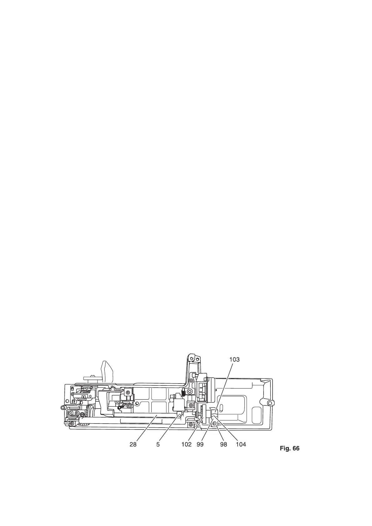
Fitting:
• Lift complete hook driving shaft 28 out of the lower right calotte bearing 103 as far as it will go
(fig. 66).
• Pull the flat toothed belt between calotte 104 and calotte bearing 103.
• Place hook driving shaft 28 exactly together with calotte 104 in the lower right calotte bearing 103.
• Fit clamping plate 99 and fasten with screw 98.
• Pull flat-toothed belt 100, which is in the inner housing, upwards (fig. 67).
• Feed arm shaft 115 from the right into the housing.
• Place flat-toothed belt 100 over arm shaft 115.
• Feed arm shaft 115 into needle bar crank 110.
• Insert arm shaft 115 into calotte bearings 113 and 114.
• Fit clamping plates 112 and fasten with screws 111.
• Check for free movement of arm shaft, if necessary establish the free movement.
• Place flat-toothed belt 100 onto the upper and lower sprockets 101 and 102 (fig. 66).
• Set the flat-toothed belt’s tension according to section 1.
• Turn the handwheel until the fastening screw of the synchronizer control cam 35 faces downwards
(fig. 68).
• At the same time pin 116 on the upper sprocket faces upwards.
• Press needle bar crank 110 against the calotte of the left calotte bearing 113 (fig. 67).
• At the same time tighten screw 109 on needle bar crank 110.
• Check for free movement of the arm shaft, if necessary establish it.
• Attach connecting rod 108.
• Mount lockwasher 54 onto the needle bar frame.
• Attach pull-spring 105.
• Attach circlip 107 to the zigzag stepping motor.
• Mount the front housing shell and fasten with torx screws 23, 24 and 25.
• Mount the rear housing shell and fasten with torx screws 12 and 13.
• Attach connection plugs 14 until 22 to the circuit board on the front housing shell.
• Locate the baseplate, the freearm lid with bobbin thread monitor and the buttonhole sensor to the
right next to the machine.
• Attach connection plug 9 to the circuit board on the front housing shell.
• Attach the needle plate.
• Attach connection plugs 4, 5 and 6 to the circuit board on the baseplate.