76
33. Changing the synchronizer circuit board
Removal:
• Remove the mains lead from the mains socket and from the machine.
• Remove the detachable work support.
• Remove the folding cover.
• Unscrew and remove both torx screws of the housing insert.
• Remove the housing insert.
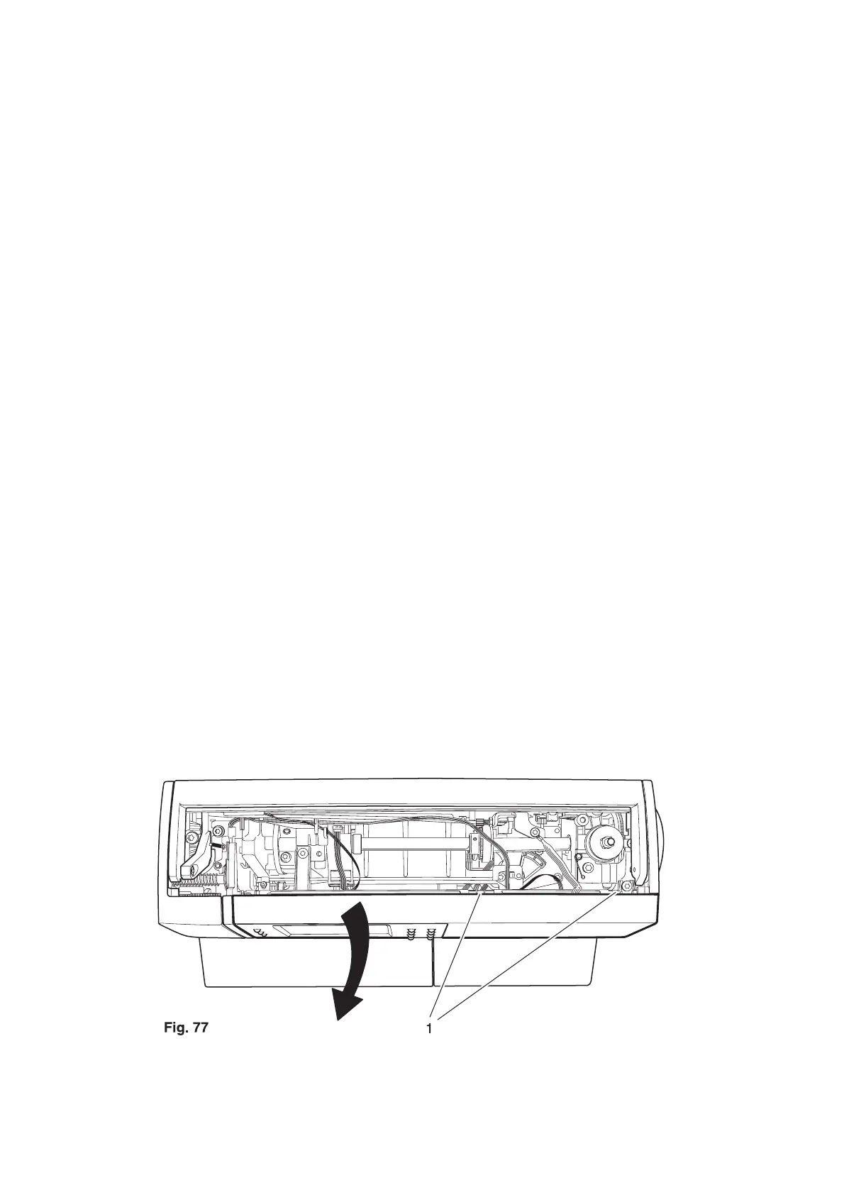
• Raise both lugs 1 slightly and remove the facing panel in the direction of the arrow (fig. 77).
• Remove connection plug 3 from the circuit board on the front housing panel (fig. 78).
• Remove the connecting wire from the cable chanel.
• Unscrew and remove fastening screw 126 on circuit board 36 using the torx offset screwdriver TX 15
(fig. 79).
• Remove the complete circuit board 36.
Fitting:
• Secure circuit board 36 to the housing with fastening screw 126, using the torx offset screwdriver
TX 15.
• Make sure that the circuit board is positioned as such, so that the cams of control cam 35 are
positioned in the middle of the circuit board guides (fig. 80).
• Insert the connecting wire of circuit board 36 through the cable chanel.
• Mount connection plug 3 onto the circuit board on the front housing panel (fig. 78).
• Mount the facing panel onto the front housing panel and make sure that both lugs 1 lock fully into
place (fig. 77).
• Adjust the synchronizer in accordance with section 5.
• Attach the housing insert and secure with both torx screws.
• Attach the folding cover.
• After a running-in time of 10 - 15 min. check the adjustment of equal forward and reverse stitch length
according to section 22 of this service manual.