72
• Pull out the mains plug and the socket on the machine.
• Remove the needle and the presser foot shoe.
• Remove the detachable work support.
• Remove the top cover.
• Unscrew and remove the two torx screws of the housing insert.
• Remove the housing insert.
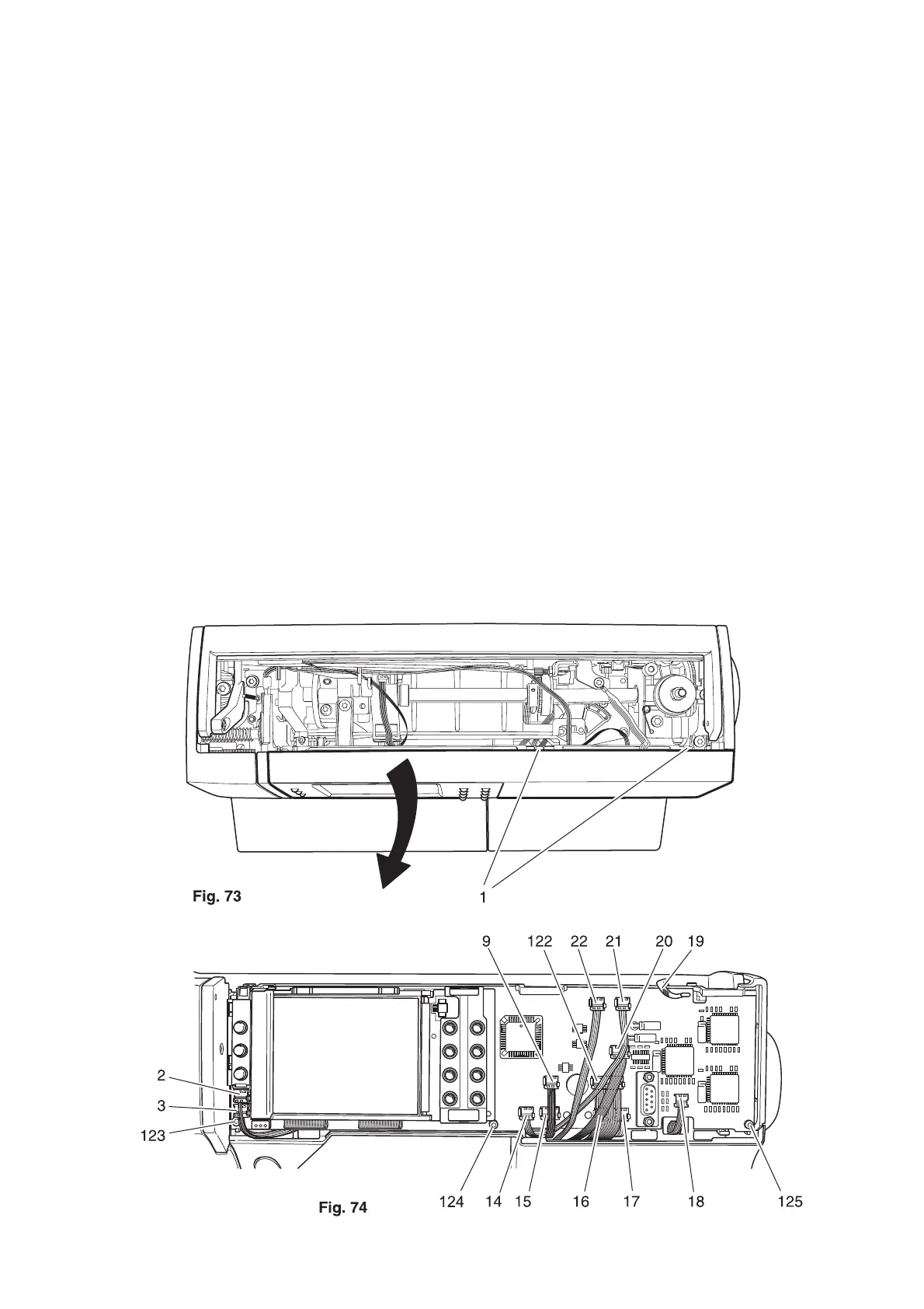
• Slightly raise both lugs 1 and remove the facing panel of the front housing panel by swiveling
it downwards (fig. 73).
• Remove connection plug 2 and 3 from the circuit board (fig. 74).
31. Changing the upper circuit board
Removal:
• Remove the green connection plug 9 from the circuit board.
• Remove the connecting plug 14 from presser bar lifter sensor.
• Remove the connecting plug 15 from button hole sensor.
• Remove the connecting plug 122 from ZZ connecting wire.
• Remove the connecting plug 16 from ZZ stepping motor.
• Remove the connecting plug 17 from feeding stepping motor.
• Remove the connecting plug 18 from speed sensor.
• Remove the ESD cable 19.
• Remove the connecting plug 20 from the knee lifter.
• Remove the connecting plug 21 from presser bar stepping motor.
• Remove the connecting plug 22 from PC board for presser bar stepping motor.
• Unscrew and remove screws 123, 124 and 125.
• Remove the complete circuit board.