List of figures
Fig. 1: Position of the labels on the product.......................................................................... 8
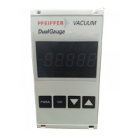
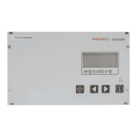
Fig. 2: DCU control panel, front view...................................................................................14
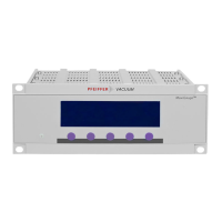
Fig. 3: DCU with integrated power supply pack, rear view.................................................. 15
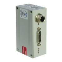
Fig. 4: DCU 002, rear view.................................................................................................. 15
Fig. 5: Connection diagram for the DCU with integrated power supply pack...................... 19
Fig. 6: Connection diagram for the DCU 002...................................................................... 19
Fig. 7: Connection of the grounding cable to the DCU with integrated power supply pack....
20
Fig. 8: Example: Connection of a DCU 002 to a vacuum pump.......................................... 21
Fig. 9: Example: Connection of a DCU with integrated power supply pack to a vacuum
pump.........................................................................................................................21
Fig. 10: LC-display, overview................................................................................................ 25
Fig. 11: Dimensions DCU 002...............................................................................................35
Fig. 12: Dimensions DCU 110...............................................................................................35
Fig. 13: Dimensions DCU 180, DCU 310, DCU 400............................................................. 35
List of figures
6/38