ErgoLine D330/D340
Customer Engineer Manual
Page 2-32
8. Replace the base and secure with screws.
9. Replace any auxiliary equipment and replace the handset plug.
10. Replace or fit the external power supply.
11. Replace the DSS/DSS cover.
12. Program the TEI to 0&1 via the Service Mode program.
13. Replace the line cord.
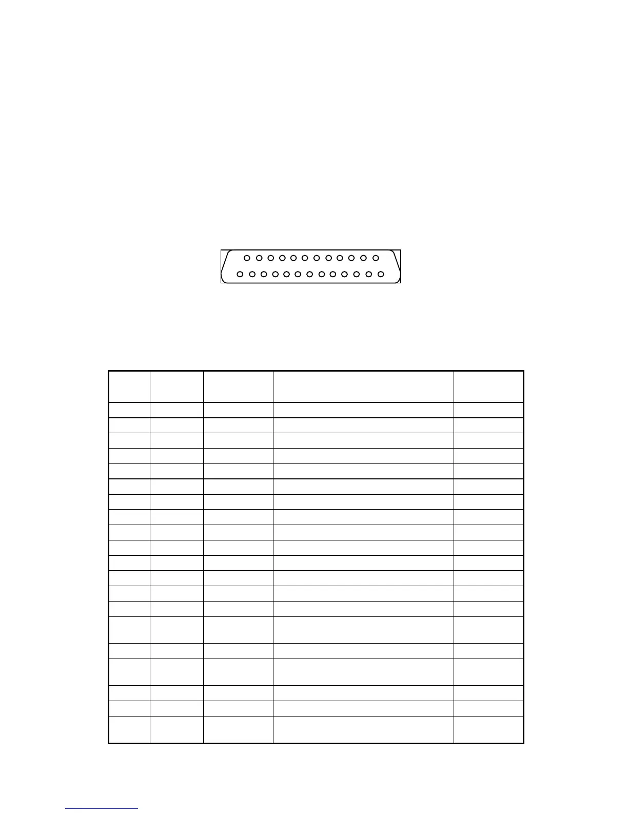
Connection to the V.24 interface is via a 25 pin D-type female connector (ISO
2110 specification) on the rear of the ErgoLine D340 main terminal unit.
F
IGURE
2-6. V.24 I
NTERFACE
C
ONNECTOR
P
IN
L
AYOUT
T
ABLE
2-7. V.24 P
IN
C
ONFIGURATION
PIN CIRCUIT MNEMONIC DESCRIPTION
DCE
1 - - N/C -
2 103 TD Transmitted data to
3 104 RD Received data from
4 105 RTS Request to send to
5 106 RFS Ready for sending from
6 107 DSR Data set ready from
7 102 GND Signal ground / common return -
8 109 DCD Data carrier detect from
9 - - N/C -
10 - - N/C -
11 - - N/C -
12 - - N/C -
13 - - N/C -
14 - - N/C -
15 114 TSET
Transmitter signal element timing
(DCE source)
from
16 - - N/C -
17 115 RSET
Receiver signal element timing (DCE
source)
from
18 141 LL Local loopback to
19 - - N/C -
20