ErgoLine D310/320
Customer Engineer Manual
Page 5-
5
Installation
Cabling
Handset Cord
The handset is connected to the ErgoLine via a four wire coiled cord which termi-
nates with a four way male modular plug at the terminal side.
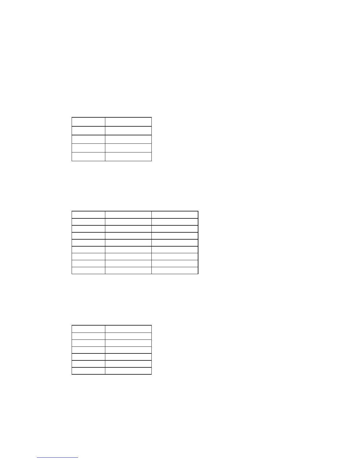
Pin Outs
Pin Signal
1 Telephone
2 Microphone +
3 Microphone -
4 Telephone
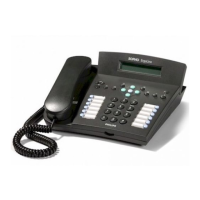
Terminal Line Cord D310-2W, D320-2W, D320-4W
On both ends the terminal line cord (normal length 6 m.) terminates with an eight
way plug. See diagram below.
Pin Outs
1 n/c n/c
2 n/c n/c
3 Transmit + n/c
4 Receive + a-wire (pos)
5 Receive - b-wire (neg)
6 Transmit - n/c
7 n/c n/c
8 n/c n/c
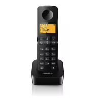
Terminal Line Cord D310-4W
On the wall plug end the terminal line cord (normal length 6 m.) terminates with
an eight way plug. See diagram above. The terminal end of the terminal line cord
ends with a 6 way plug. See diagram below.
Pin Outs
1 n/c
2 Transmit +
3 Receive +
4 Receive -
5 Transmit -
6 n/c
Note:
For more information on the hardware configuration of the
corresponding boards, see the Maintenance Manual for the iS3000, Part 3
Board Interfaces and Strap Settings, Chapter 4.