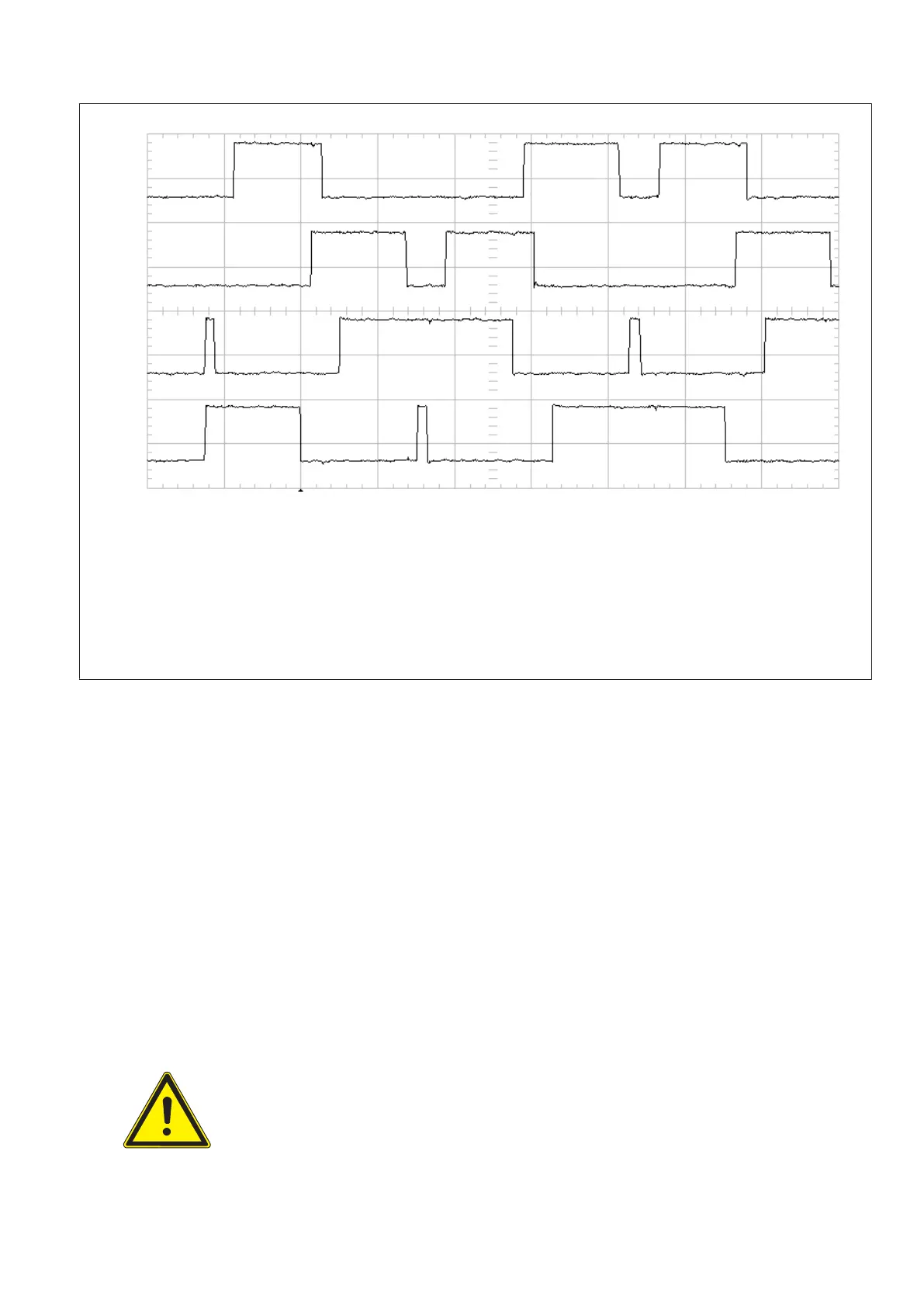
Ch 4 = Y100 x8 gate IGBT V3
Ch 3 = Y100 x7 gate IGBT V2
Ch 2 = Y100 x9 gate IGBT V4
Ch 1 = Y100 x6 gate IGBT V1
Average high level = +3.6V
Average high level = +1.2V
Whenever IGBT signals x6 (V1) + x9 (V4) or x7 (V2) + x8 (V3) are active high new energy is driven into the system.
V1 + V2 or V3 + V4 must never be active high = on together.
Signals from top to down, voltage scale for Ch1 only, active state high:
4.0
2.0
0.0
-2.0
-4.0
-6.0
-8.0
-10.0
-12.0
Input B
-40
µ
s 20
µ
s/Div
(Fig. 8)
Test 3: Comparison of control signals of EQ with E2Q: only for w 65 kW
Test 3: only for 65/80/100kW with two kV power units:
▪ Compare control signals of both units.
The signals at R25 of unit 1 must be absolutely equal to the signal at R25 at unit 2.
▪ If no problems are visible = all wave forms are as they should be:
▪ Switch off the generator with ENF1.
▪ Remove links EN_X_C/ and CTRL_X_C/ at the backpanel X76 and X74.
▪ Remove oscilloscope probes.
▪ Close the kV power part(s).
▪ Connect mains power lines at ENK1:1 :3 :5.
▪ Switch on ENF1 and the generator.
If the kV-driver test is successful prepare the generator for a next test:
WARNING
Switch OFF the generator .
Cut the generator completely from mains.
Converter test kit OPTIMUS for OPTIMUS 50/65/80 gen‐
erators release 3.x with converters 4512 104 7231x
22 CSIP Level 1 (08.0)
© 2008 Koninklijke Philips Electronics N.V.
ALL RIGHTS RESERVED
Conv test Optimus