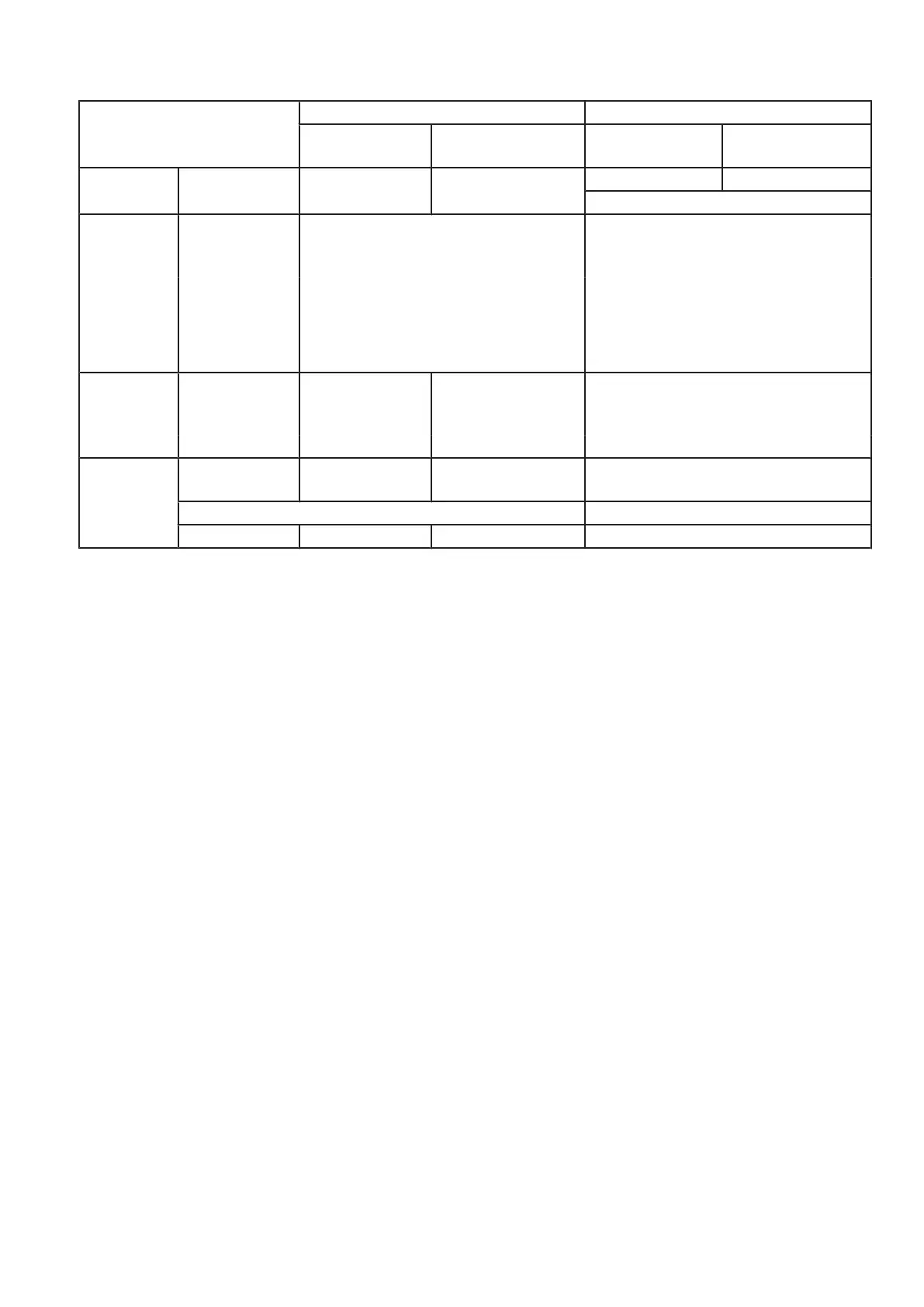
Exposures to be switched with
50mA 10ms or 0.5mAs
Measuring results
Actions
+ ►analysis
Anode
EZ130 X4
Cathode
EZ130 X5
HV cable Tube
case 1 one exposure 50% of set kV 50% of set kV ► OK ► OK
increase kV by 10kV
case 2 1
st
exposure 0 ≠ anode kV < cathode kV ≠ 0
or
0 ≠ anode kV > cathode kV ≠ 0
interchange
anode and cathode HV cables
(at both sides, tube and transformer)
2
nd
exposure no change of measured levels:
► tube defective
measured levels change:
► HV cable(s) defective
case 3 1
st
exposure set kV or 0kV 0kV or set kV
interchange
anode and cathode HV cables
(at both sides, tube and transformer)
2
nd
exposure 0kV or set kV set kV or 0kV ► HV cable at the 0kV side defective
case 4 1
st
exp. 40kV 0kV 0kV
remove anode HV cable from tube
and
HV transformer side
!! this test with 40kV only, no higher kV !!
2
nd
exp. 40kV 40kV or 20kV 0kV or 20kV ► tube defective
▪ Compare measuring results with examples of oscilloscope charts on next page.
▪ Remove test cables with resistor and diode!
Converter test kit OPTIMUS for OPTIMUS 50/65/80 gen‐
erators release 3.x with converters 4512 104 7231x
Conv test Optimus CSIP Level 1 (08.0)
© 2008 Koninklijke Philips Electronics N.V.
ALL RIGHTS RESERVED
27