onlinecomponents.com
Description of the Inline Controller
7805_en_02 PHOENIX CONTACT 2-13
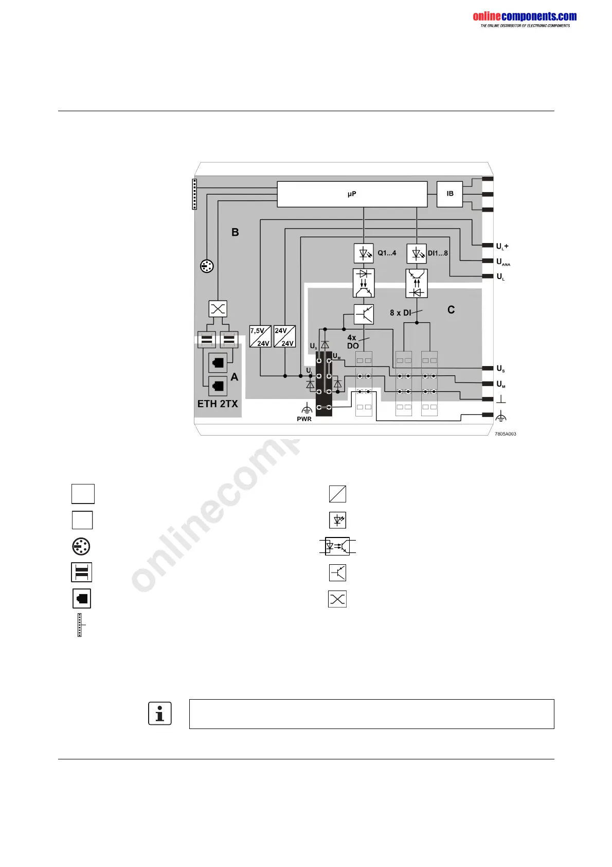
2.10 Internal basic circuit diagram
Figure 2-10 Internal basic circuit diagram (ILC 170 ETH 2TX)
Key:
The gray areas in the basic circuit diagram represent the electrically isolated areas:
A: Ethernet interface
B: Logic
C: I/O
Microprocessor Converter
Protocol chip LED
V.24 (RS-232) interface Optocoupler
Transmitter NPN transistor
RJ45 female connector Ethernet switch
SD card holder (the SD card is not supplied as standard)
µ P
I B
Other symbols used are explained in the IL SYS INST UM E user manual.
 Loading...


