onlinecomponents.com
Description of the Inline Controller
7805_en_02 PHOENIX CONTACT 2-29
2.15 Power supply
2.15.1 Sizing of the power supply
Use a power supply unit suitable for the currents in your application. The selection depends
on the bus configuration, the resulting maximum currents, and the type of supply (separate
supply of U
ILC
, U
M
, and U
S
, or supply from a power supply unit).
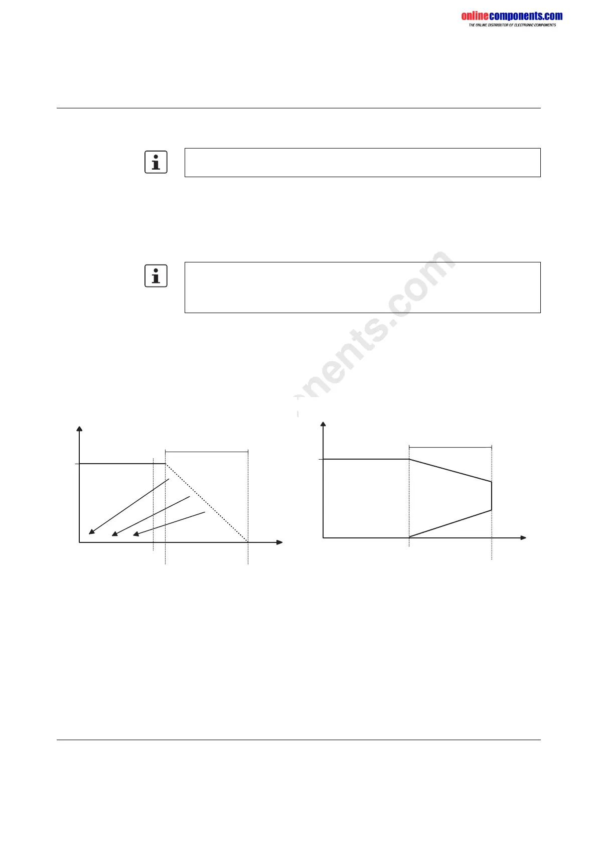
Some electronically controlled power supplies have a fall-back characteristic curve
(see Figure 2-21). They are not suitable for operation with capacitive loads.
A primary-switched power supply unit (without fall-back characteristic curve) from the
QUINT POWER range (see Phoenix Contact INTERFACE catalog) is recommended for
Inline Controller operation.
The descriptions for the power supply apply to all the Inline Controllers listed on the inner
cover page of this manual.
A power supply without a fall-back characteristic curve must be used for correct
operation of the Inline Controller (see Figure 2-22).
When the Inline Controller is switched on, an increased inrush current is temporarily
triggered. The Inline Controller behaves like a capacitive load when it is switched on.
Figure 2-21 Overload range with fall-back characteristic
curve
Figure 2-22 Overload range without fall-back
characteristic curve
U
o u t
[ V ]
I
N
~
~
1 . 1 x
I
N
2 . 4 x
I
N
~
~
I
o u t
[ A ]
2 4
O v e r l o a d r a n g e
w i t h f a l l - b a c k
c h a r a c t e r i s t i c c u r v e
6 2 1 9 A 0 7 0
U
o u t
[ V ]
I
N
1 . 5 x
I
N
~
~
I
o u t
[ A ]
2 4
O v e r l o a d r a n g e
w i t h o u t f a l l - b a c k
c h a r a c t e r i s t i c c u r v e
6 2 1 9 A 0 7 1
 Loading...


